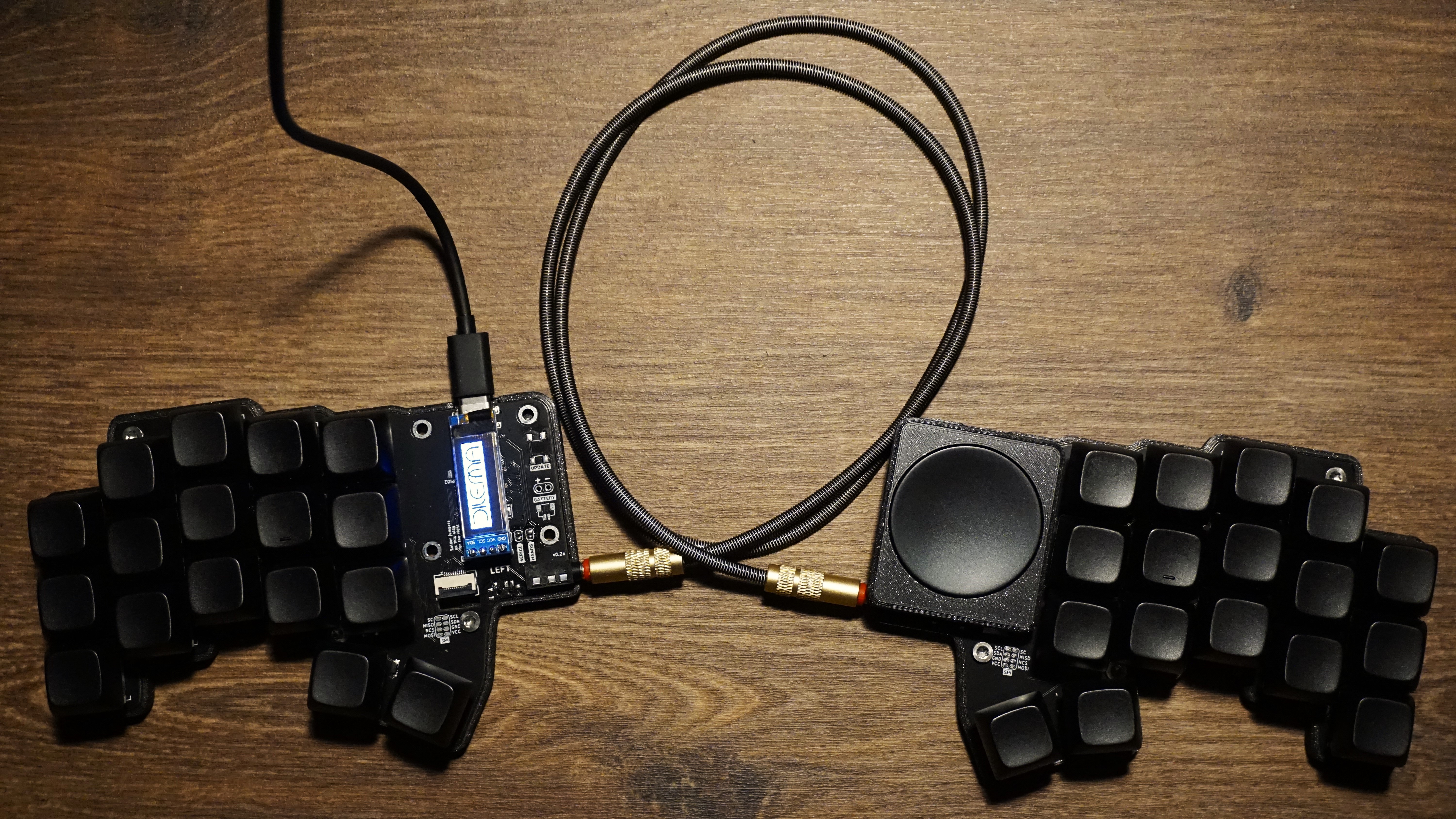
Dilemma assembled version 0.2a
Contents:
Dilemma
A week ago I received my latest project: The Dilemma. It is a low profile keyboard made by BastardKB, which currently has not been fully released yet. The files and BOM are available on GitHub, so it is possible to order them through any PCB manufacturer.
The Dilemma comes in 2 flavours: DIY or assembled. The assembled version has some elements like an RP2040, the USB C port, diodes and FPC connector already soldered on. While the DIY needs a MCU like a Sparkfun Pro Micro RP2040, nice!nano to make it wireless or other MCUs, and still needs the diodes to be soldered. With both versions you’ll need to solder the reset buttons, to be able to reset the MCU easily. In case of using nice!nanos the audio jacks are also optional, otherwise those need to be soldered too. The one I build here is the assembled version.
I received a kit from BastardKB consisting of v0.2a of the assembled version and used some switches, keycaps, and other parts which I had lying around from earlier builds.
I have been using it as a daily driver at the office to test it out, but as I am used to having 3 thumb keys, it has been a bit of a challenge, nonetheless it is an awesome little keyboard and great seeing much love for the Cirque trackpad and RP2040 microcontrollers lately.
Kit content
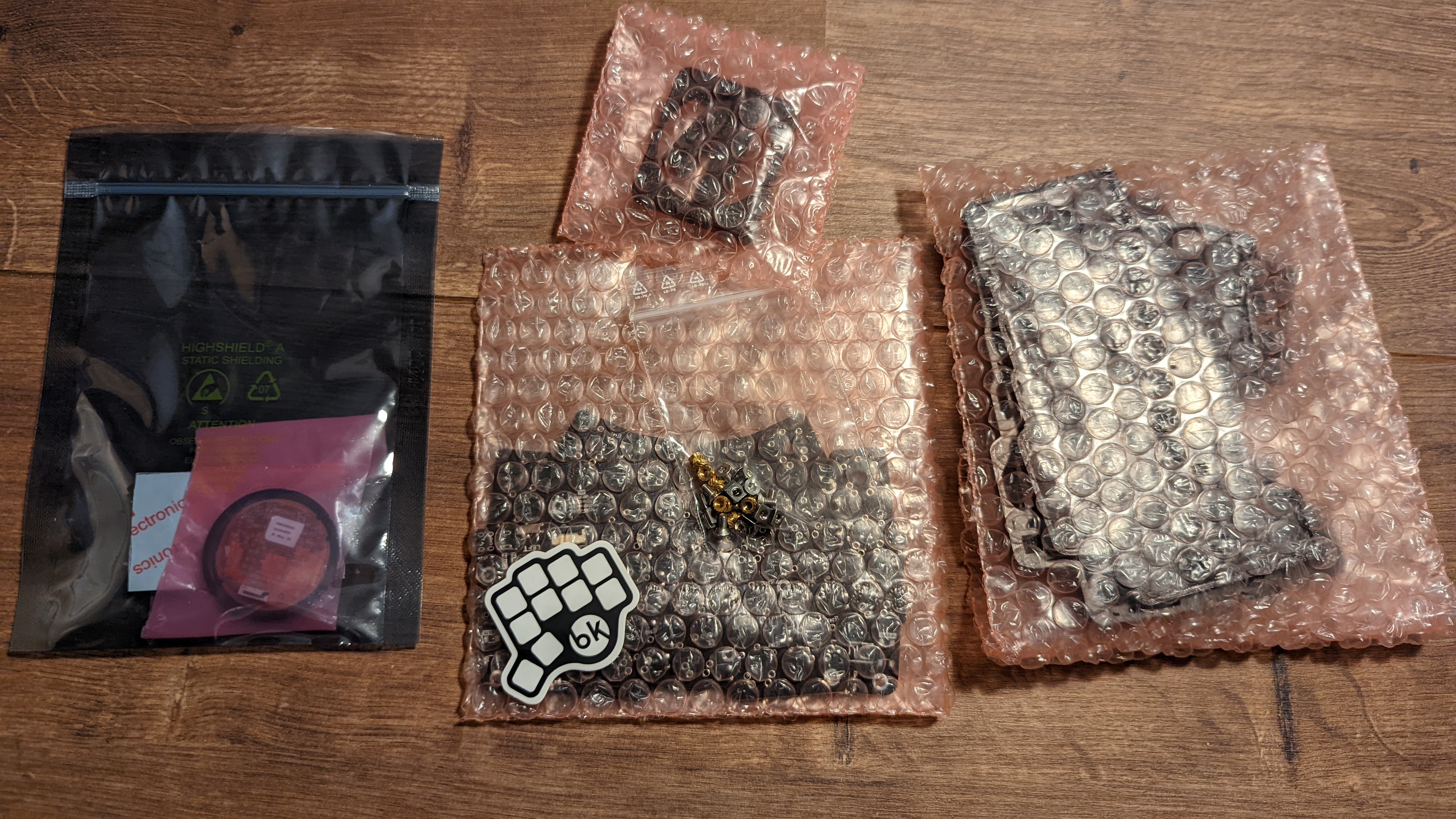
The kit I received consisted of the following parts:
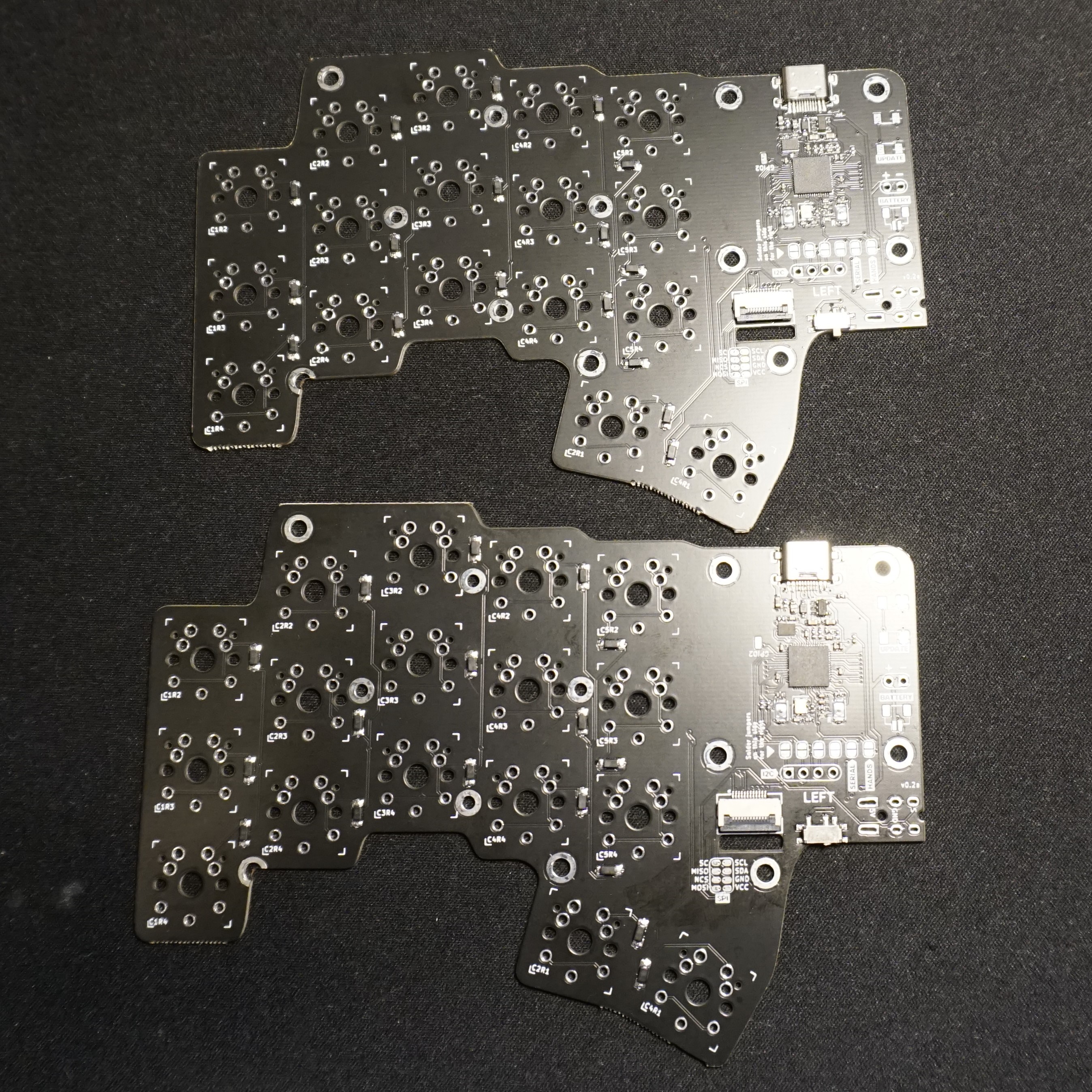
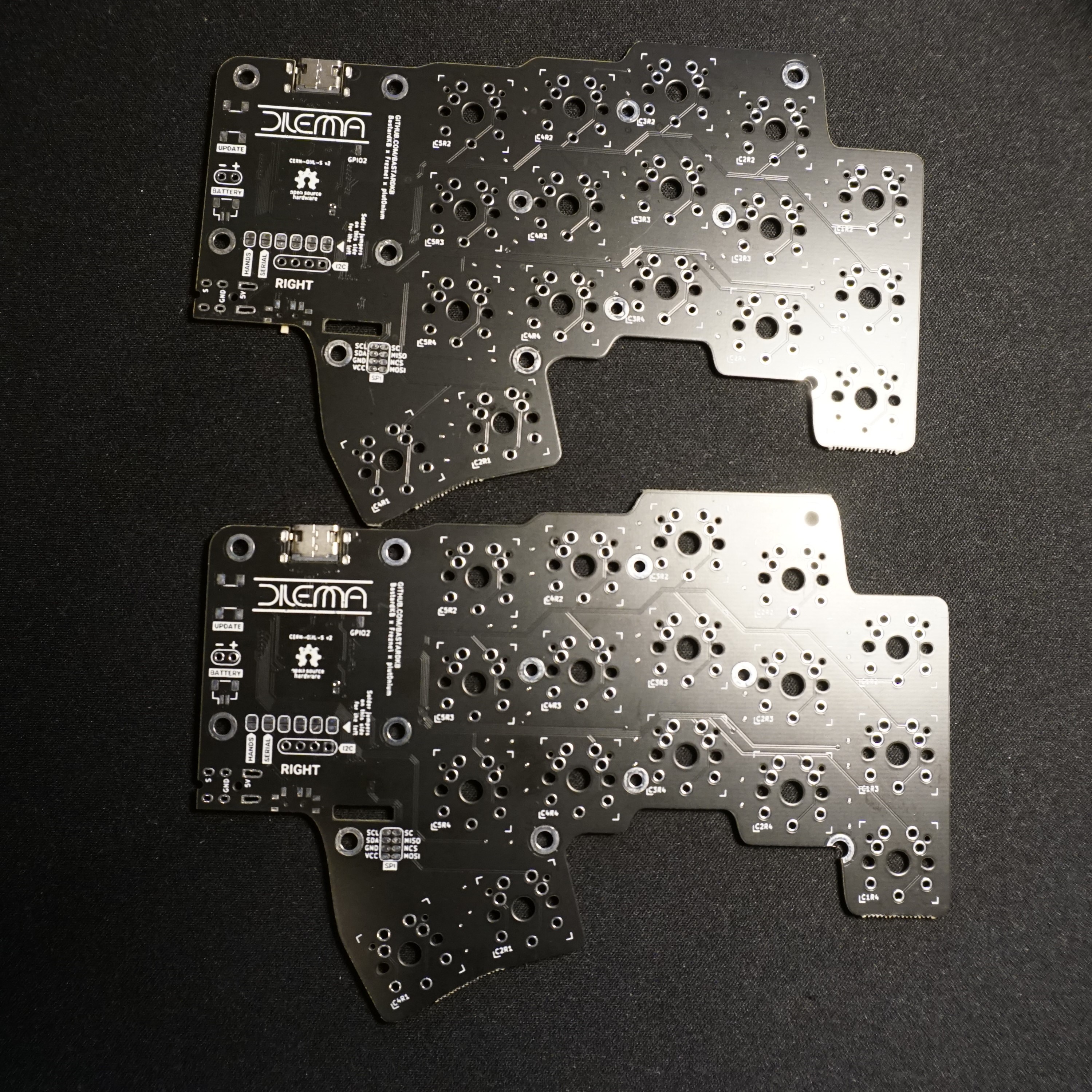
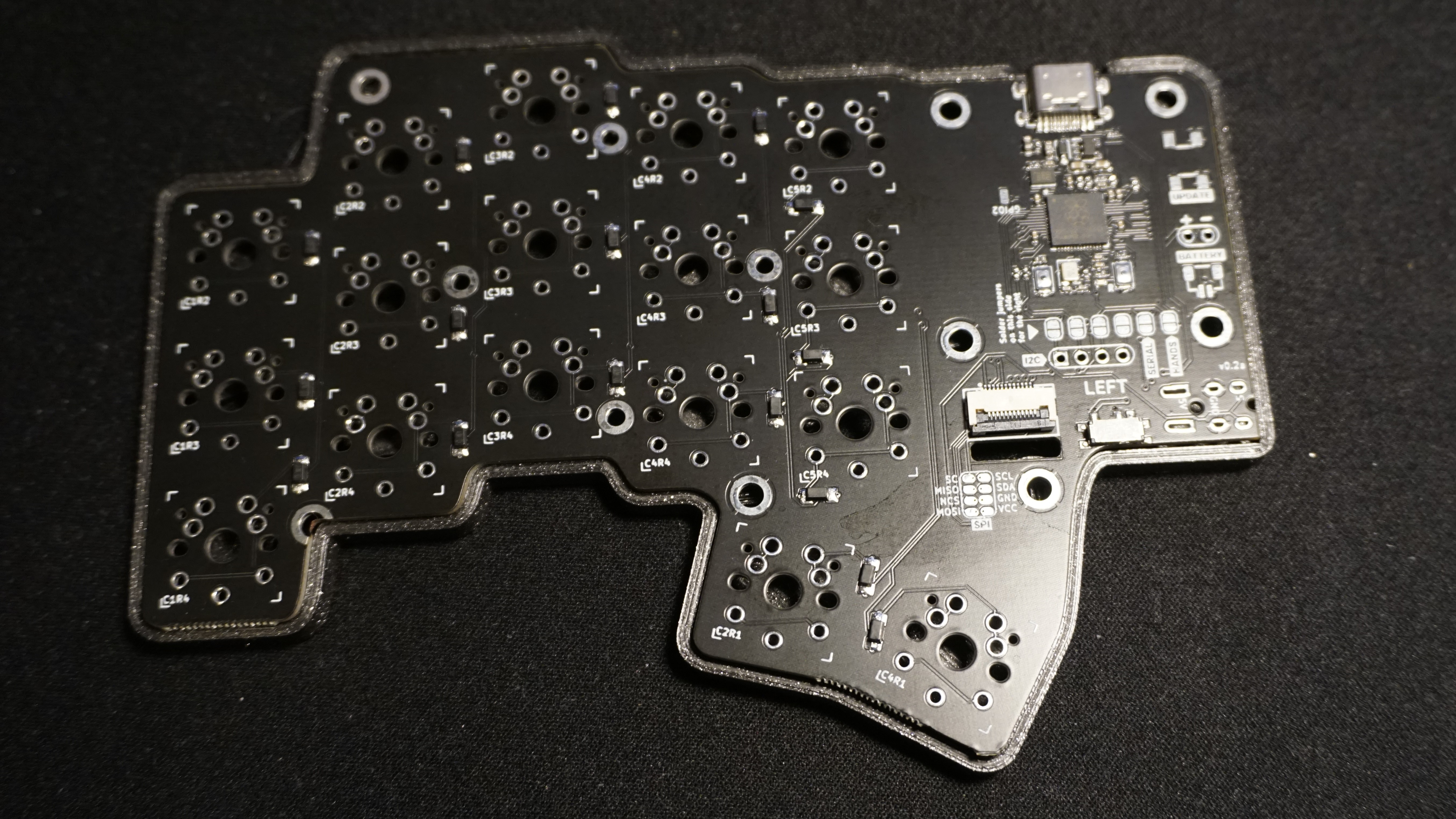
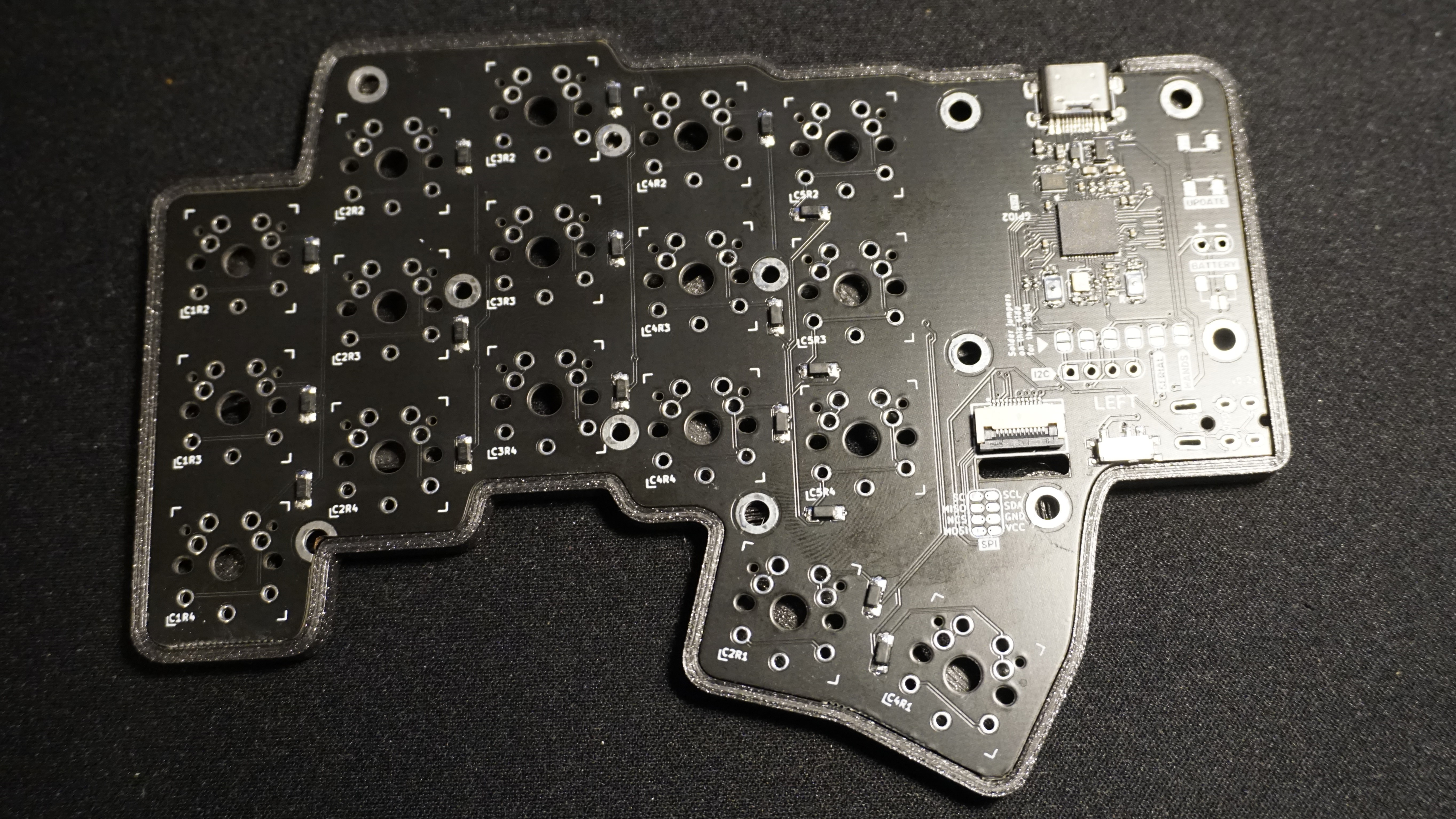
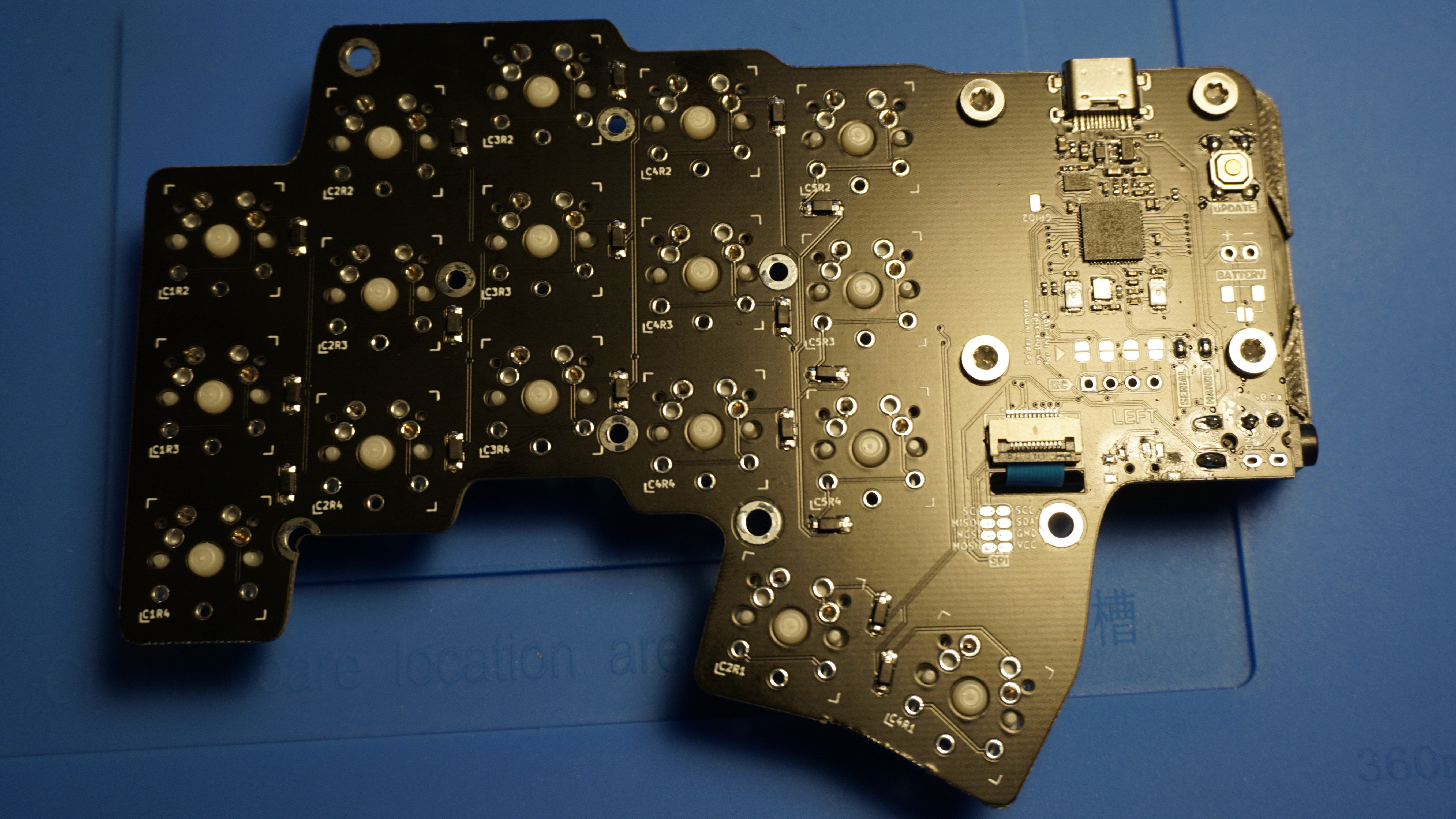
PCBs
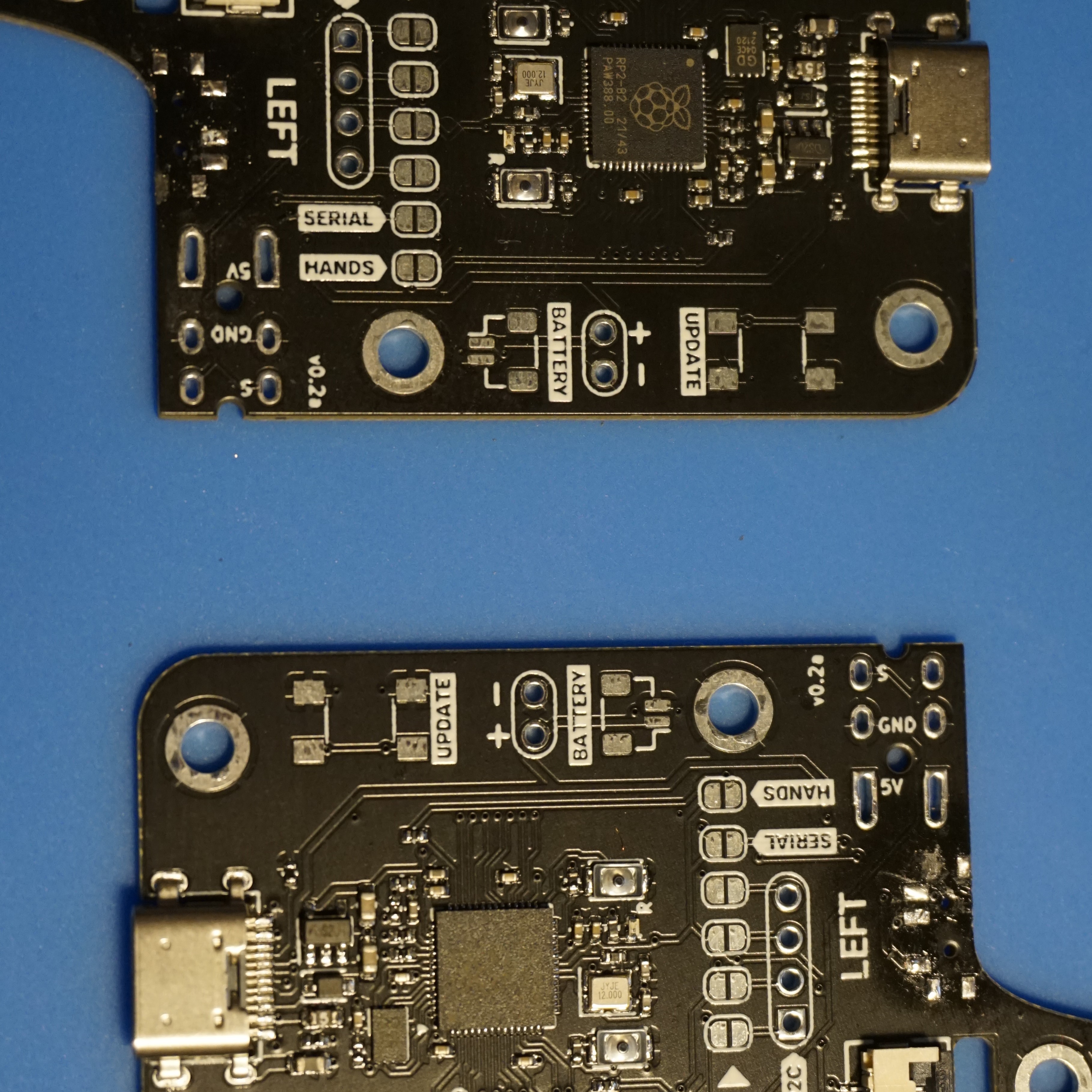
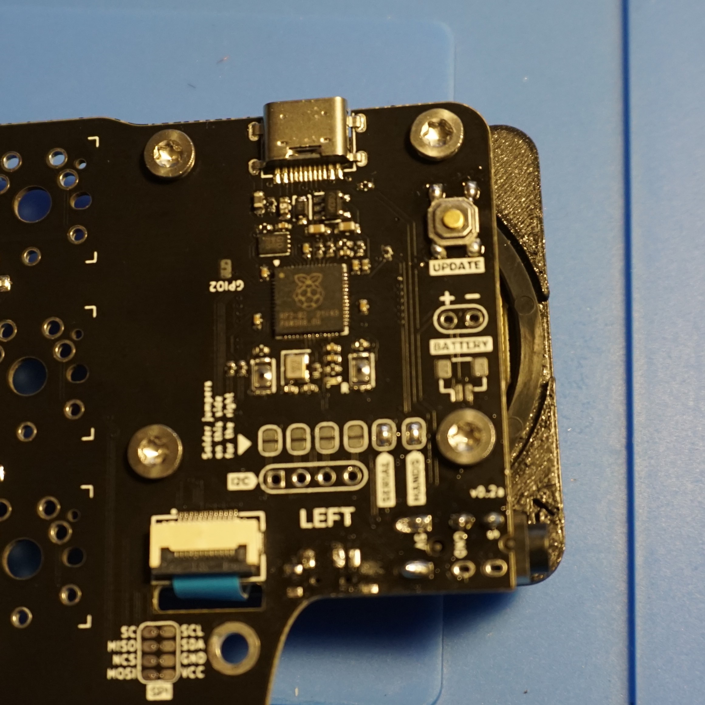
This version has reversible PCBs, meaning the MCU will be on the top of the left half, but at the bottom for the right half. As the USB C port is not completely mid-mount, it sitting at a very slightly different height for each side.
As you can see on the picture the PCB has a battery connector pads and power switches, which are actually unused on this version. The power switch also prevents the PCB from sitting flush in the case, so I removed those as I will show later.
Reset buttons
Audio jacks
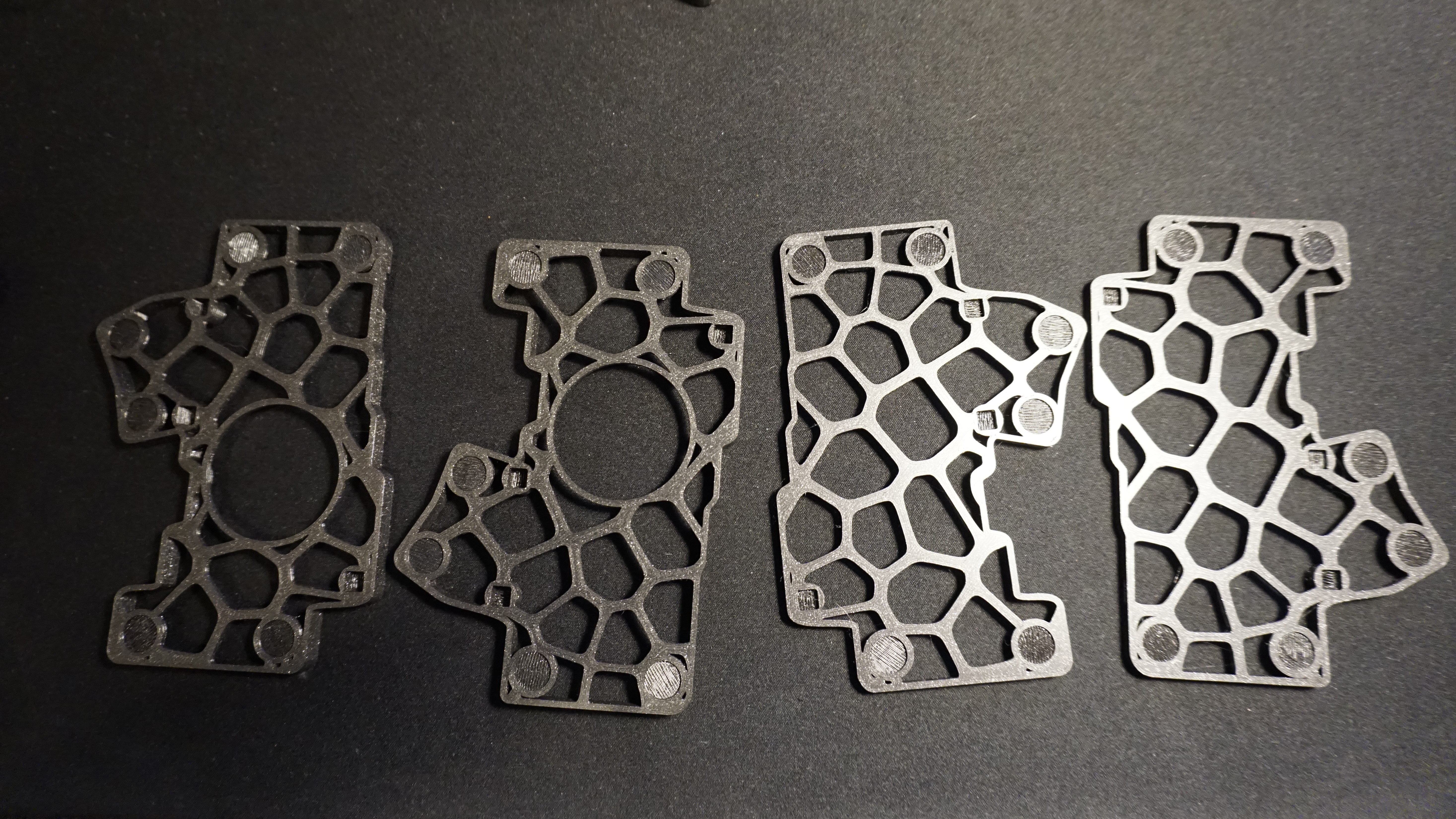
3D Cases (Thin model and SplitKB Tenting Puck model)
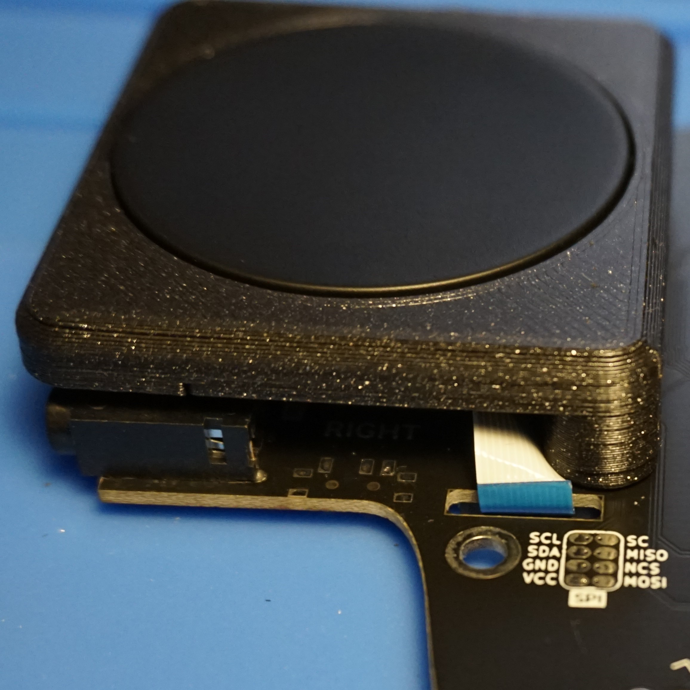
There are 2 different cases for the Dilemma: One has a hole to support the SplitKB tenting puck while the other doesn’t and is thinner. On the second picture you can see the height difference: the 2 halves of the thin case stacked on top of eachother is almost as high as a single half of the tenting case.
Mounting hardware for the case
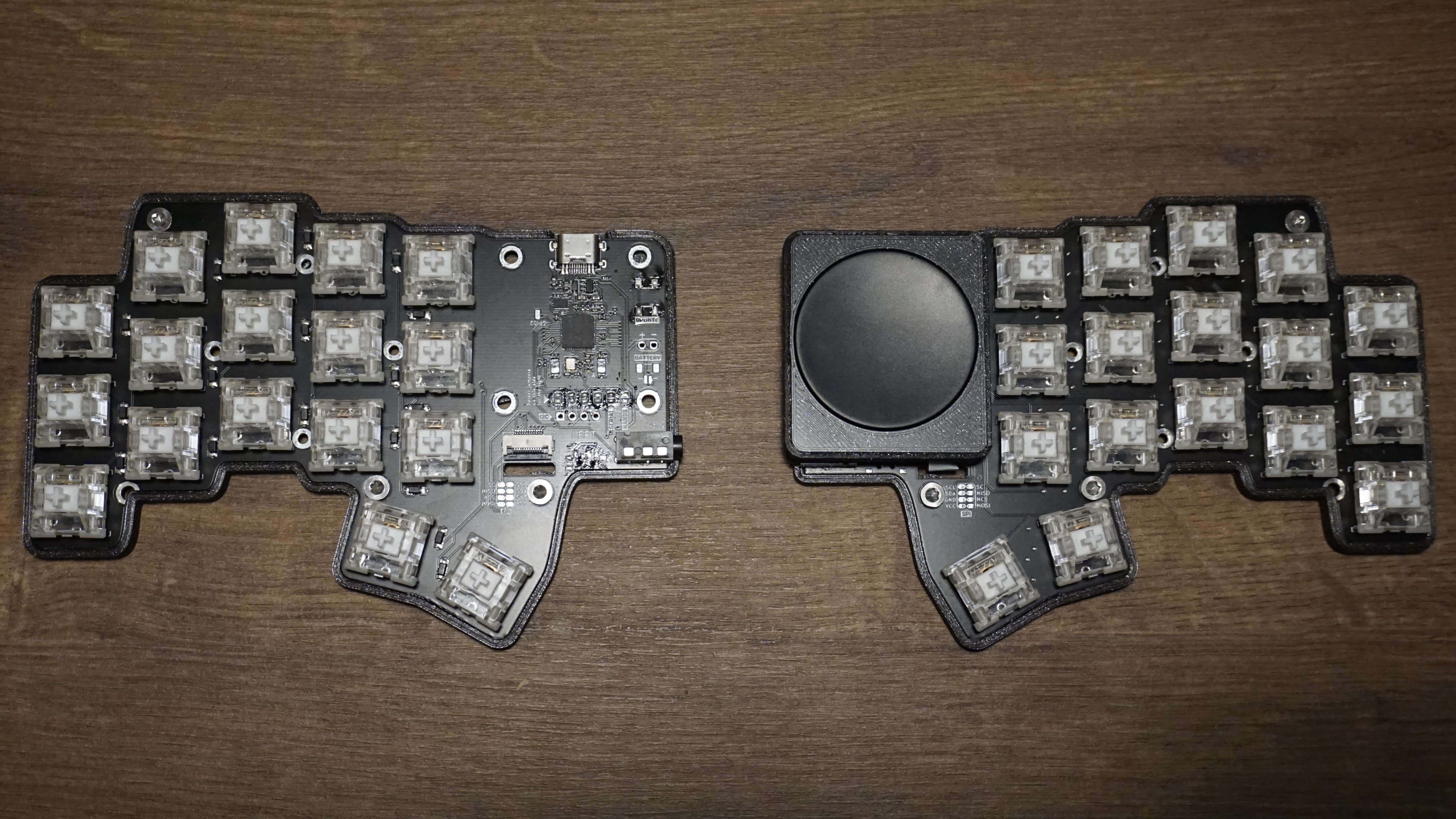
Cirque GlidePoint® Circle Trackpad Curved 35mm
FPC cable
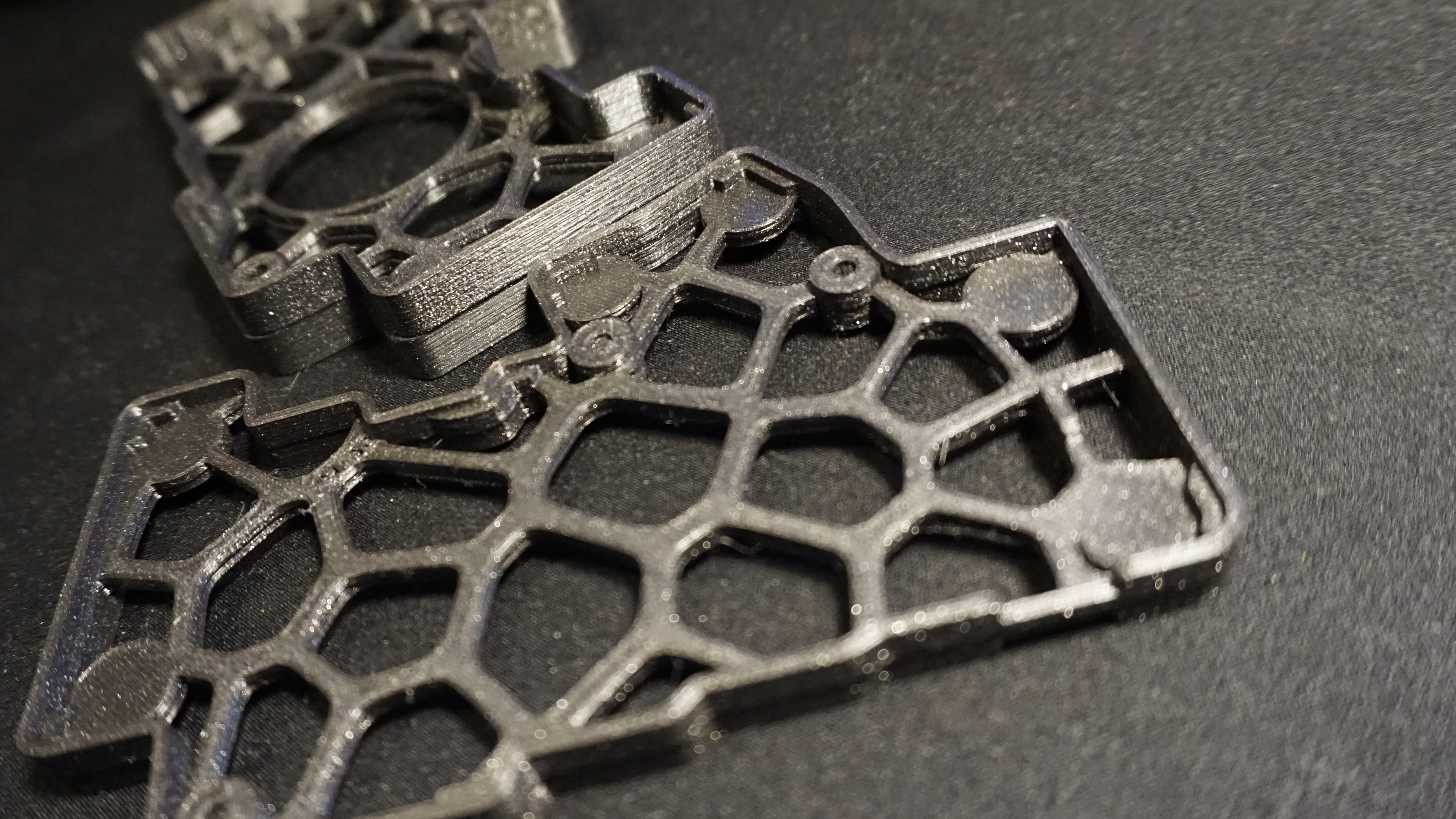
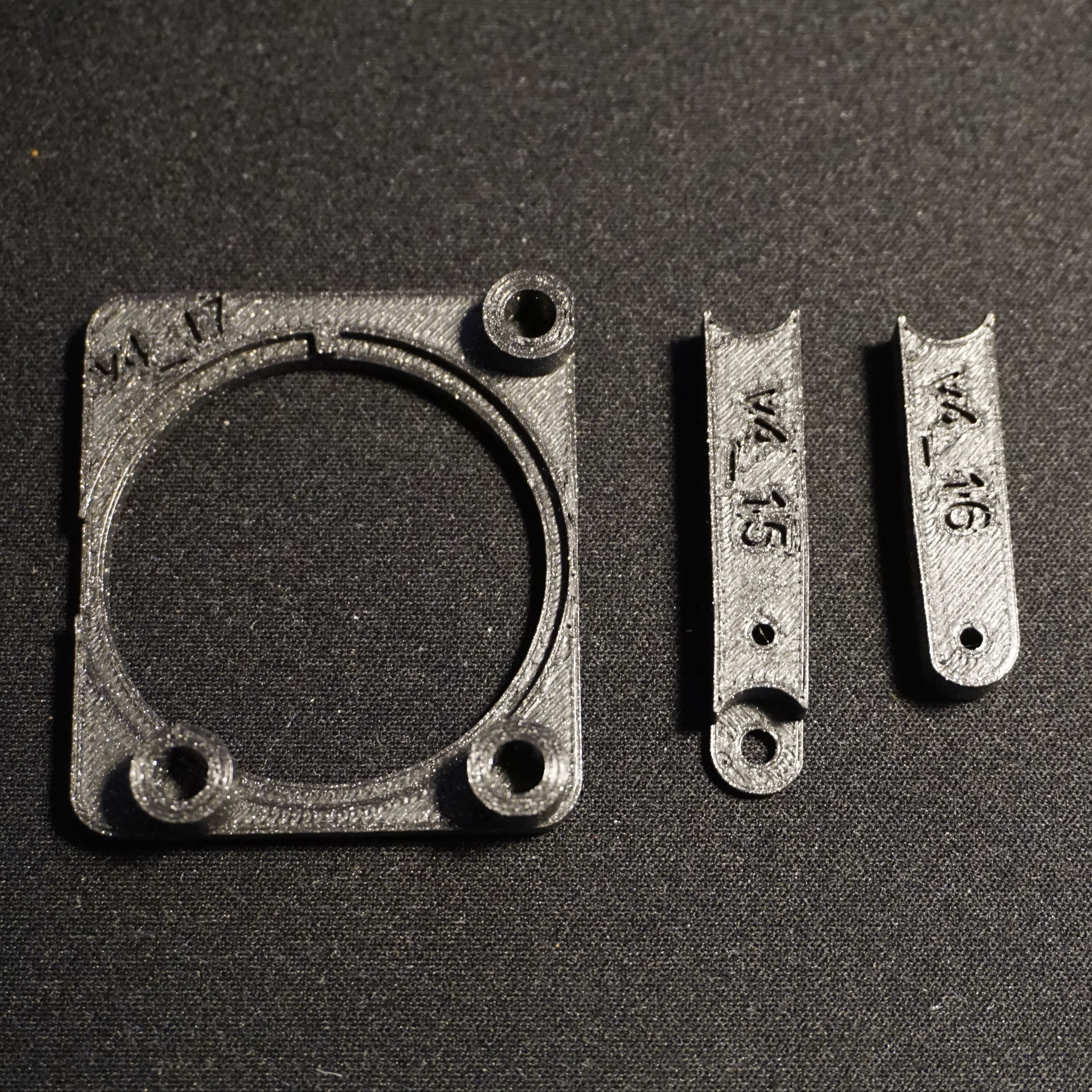
3D printed trackpad parts
Mounting hardware for the trackpad
Anti slip pads
Note that the contents of the kit might change at a later stage.
Build notes
Diodes
On this version of the Dilemma the diodes come pre-soldered, so we’re done here.
Mouse bites
These PCBs have an issue with mouse bites, which caused the PCB not fitting inside the case. To fix this I used a file to remove the mousebites.
Power switches
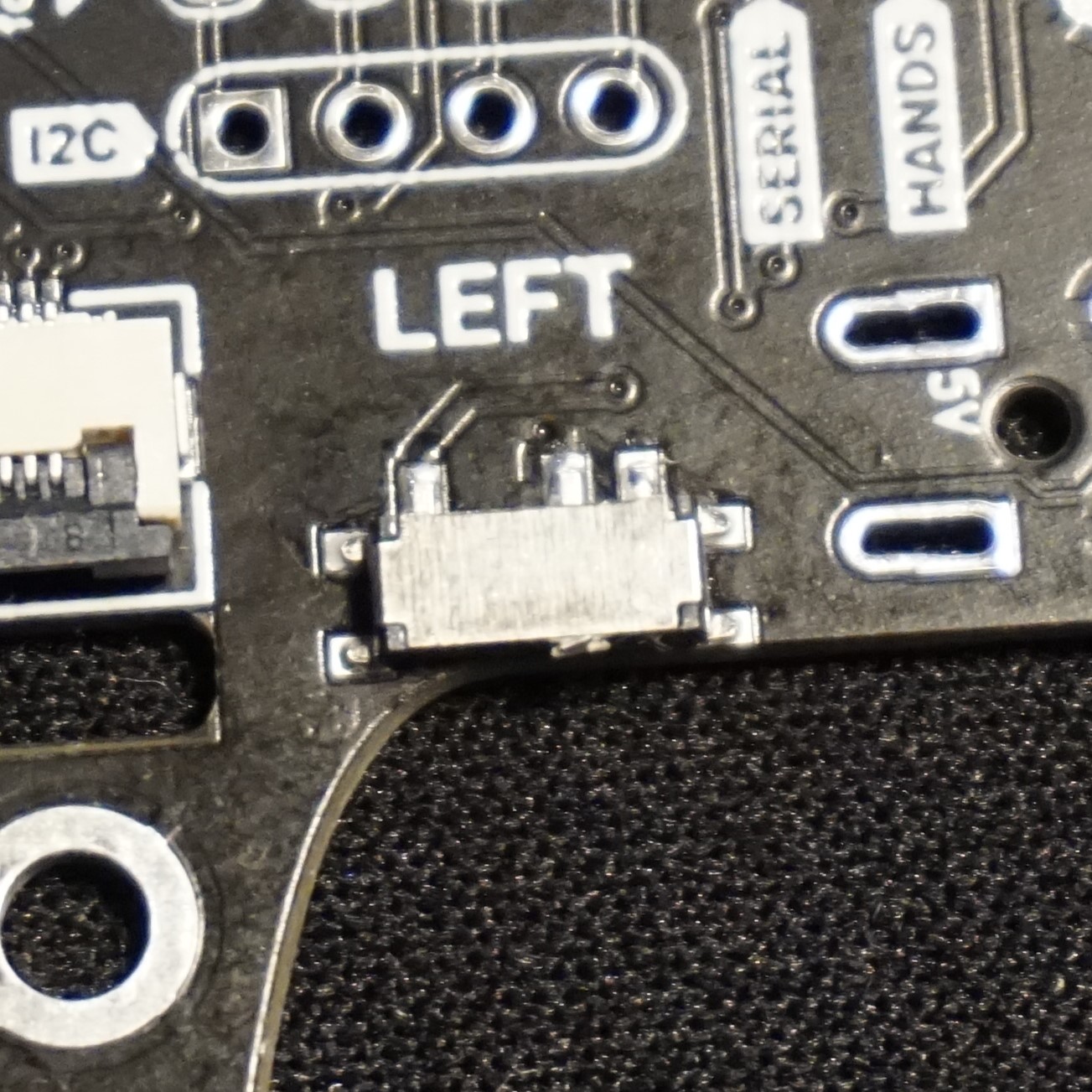
These PCBs have power switches soldered on, these prevented the PCB from being inserted properly inside the case for one half. One of the switches was actually broken already, but they are unused for this version anyway, so I decided to desolder them. I need to work on my desoldering skills as I actually seem to have removed some pads, good thing we don’t need these.
Reset buttons and bridging jumpers
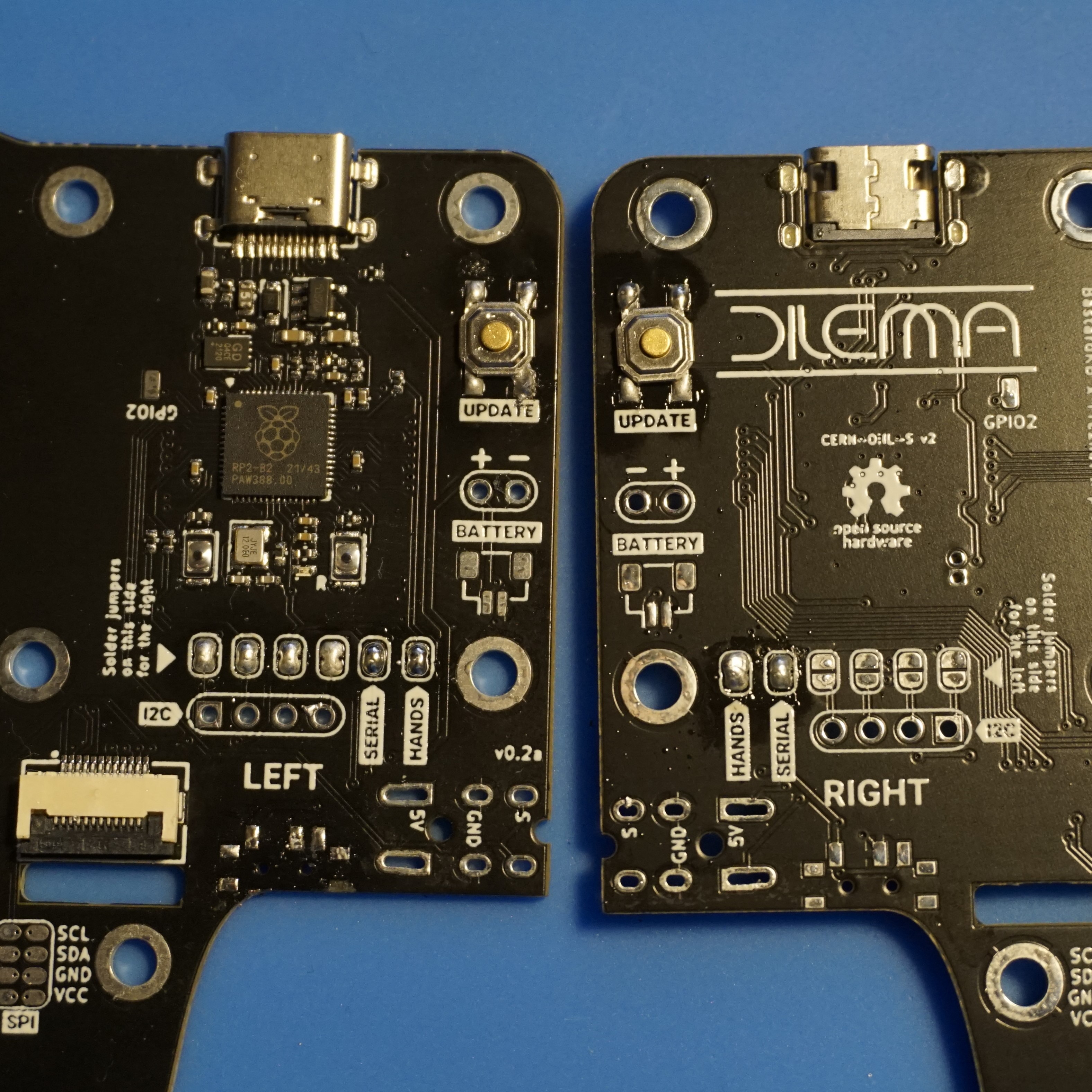
Soldered the reset button and bridged the Serial and Hands jumpers as well as the I2C jumpers. I actually soldered those on the wrong side at first, I soldered them on the topside instead of the bottom side, so that’s the reason why you can see some leftover solder on later photos. Note to self to carefully read and look at the photos of the build guide, multiple times!
Audio jacks
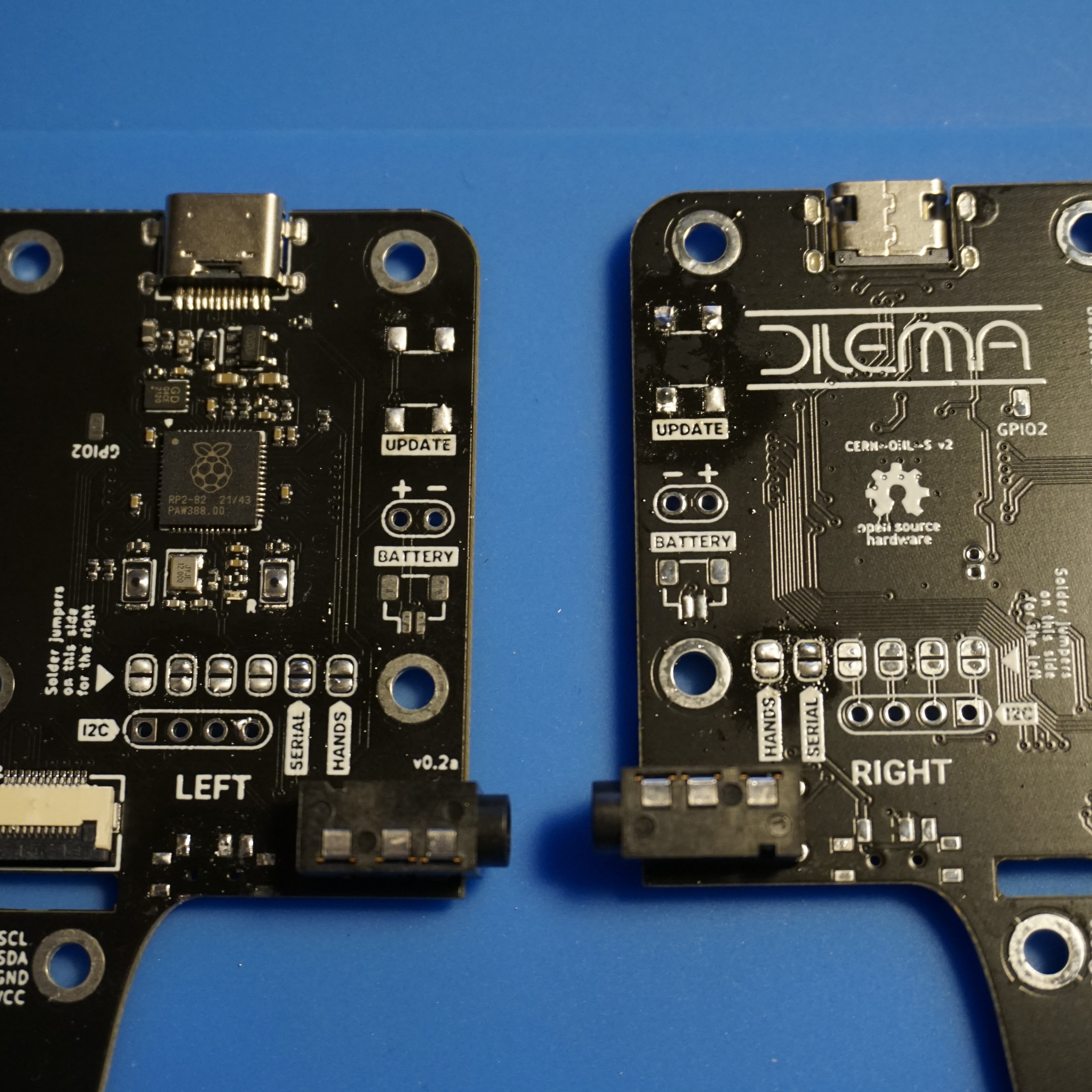
Soldered the audio jacks. I also made a mistake here by soldering those on the bottom instead of the top. I guess it’s not a good idea to do builds this late at night.
Since I find desoldering reset buttons and unbridging pads are easier than desoldering audio jacks, I decided to fix it that way. So that’s why some leftover solder is visible on the reset button pads.
Screw inserts
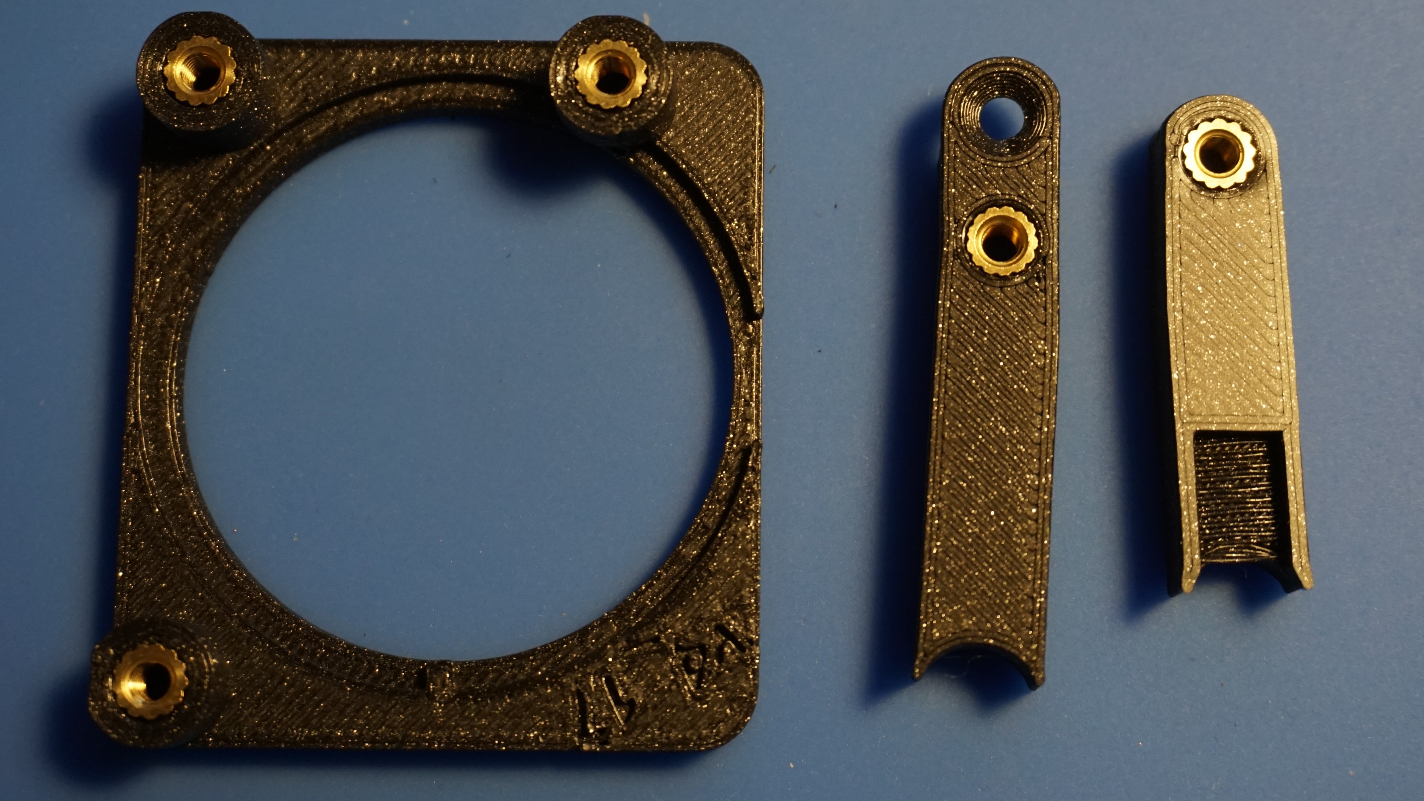
Installed the screw inserts into the trackpad assembly by placing them with a hot soldering iron into the holes. When they are almost all the way in, I use the back of my (metal) screw driver to push them flush.
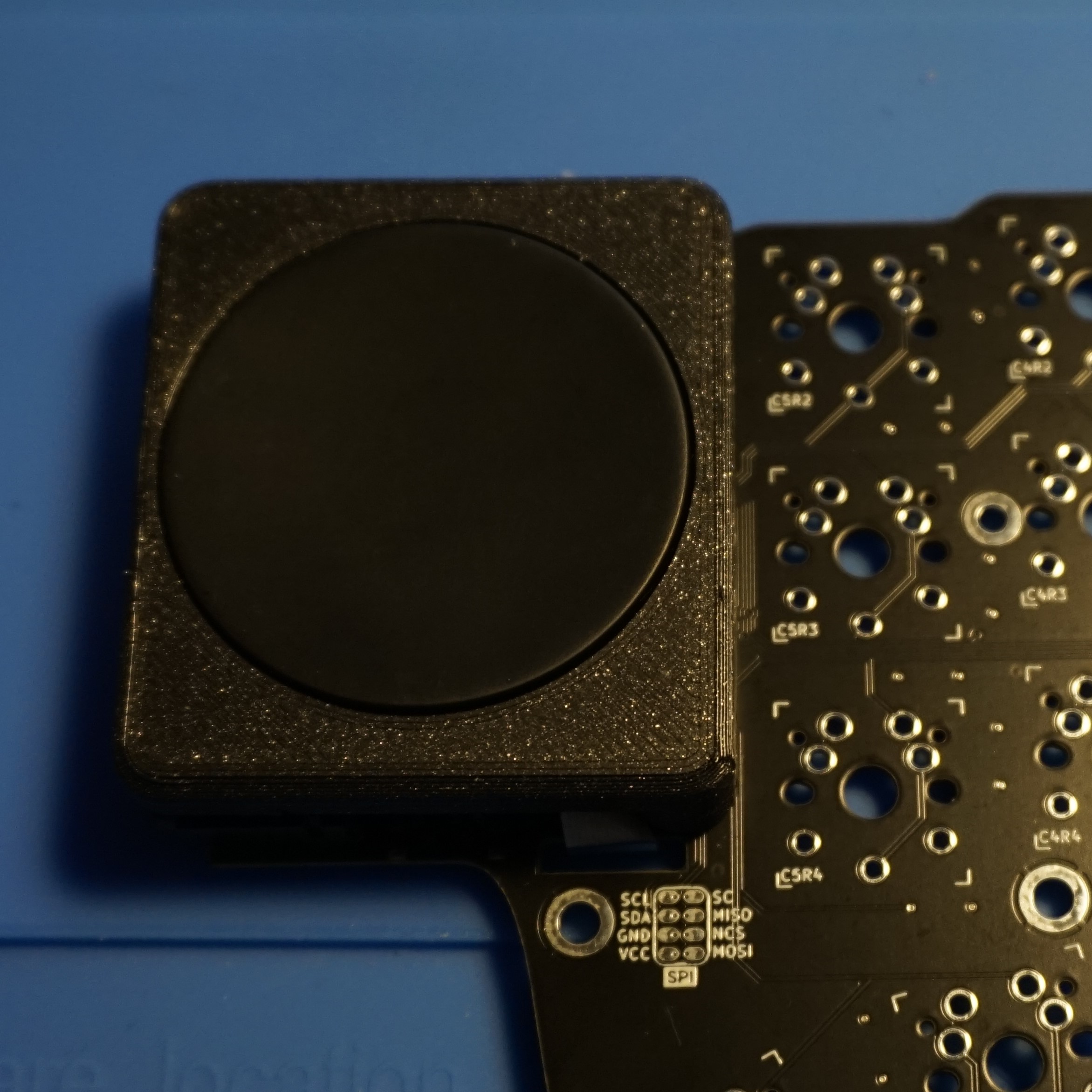
Trackpad
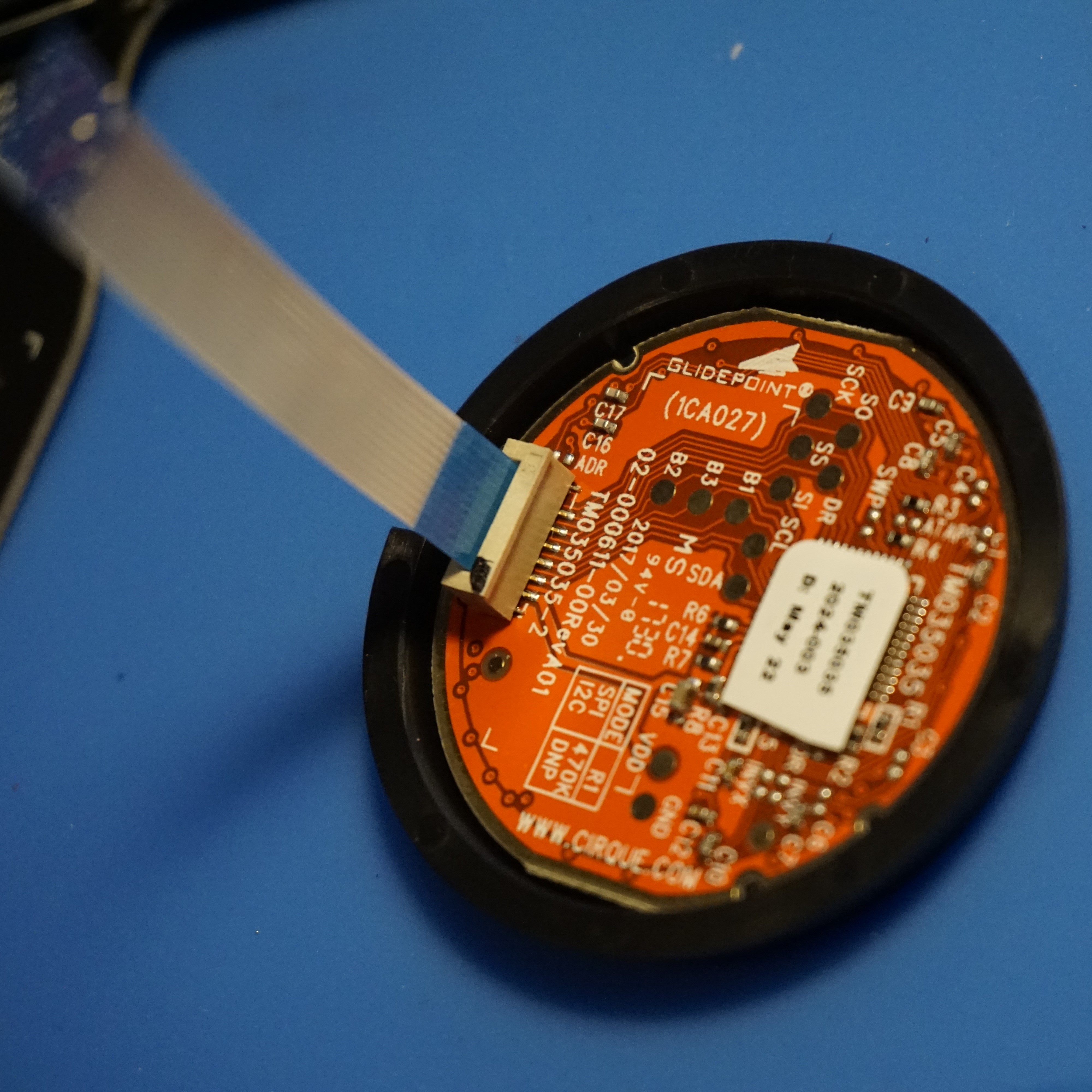
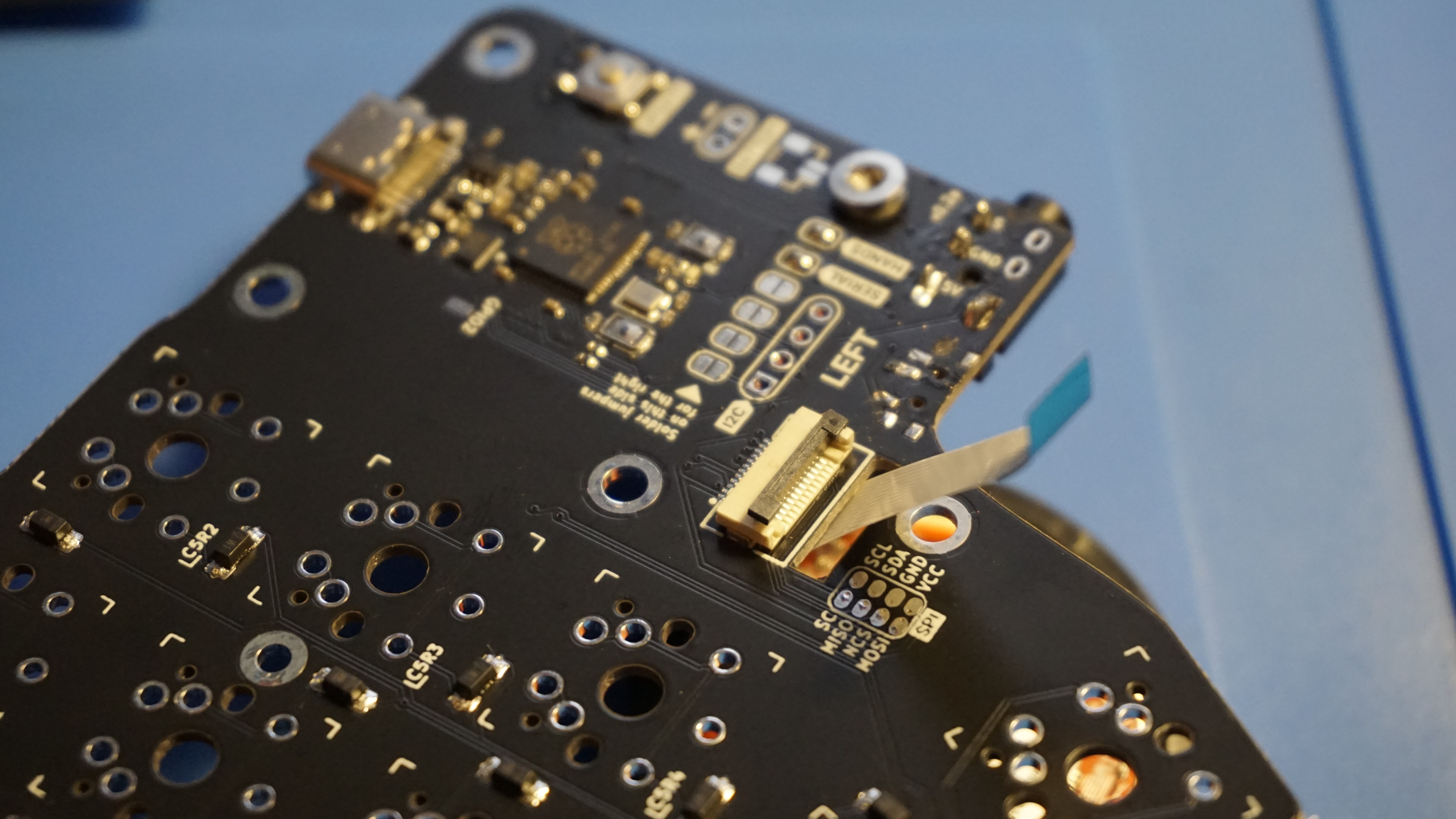
Installed the FPC cable on the trackpad, pass the cable through the PCB and install insert it in the connector on the pcb.
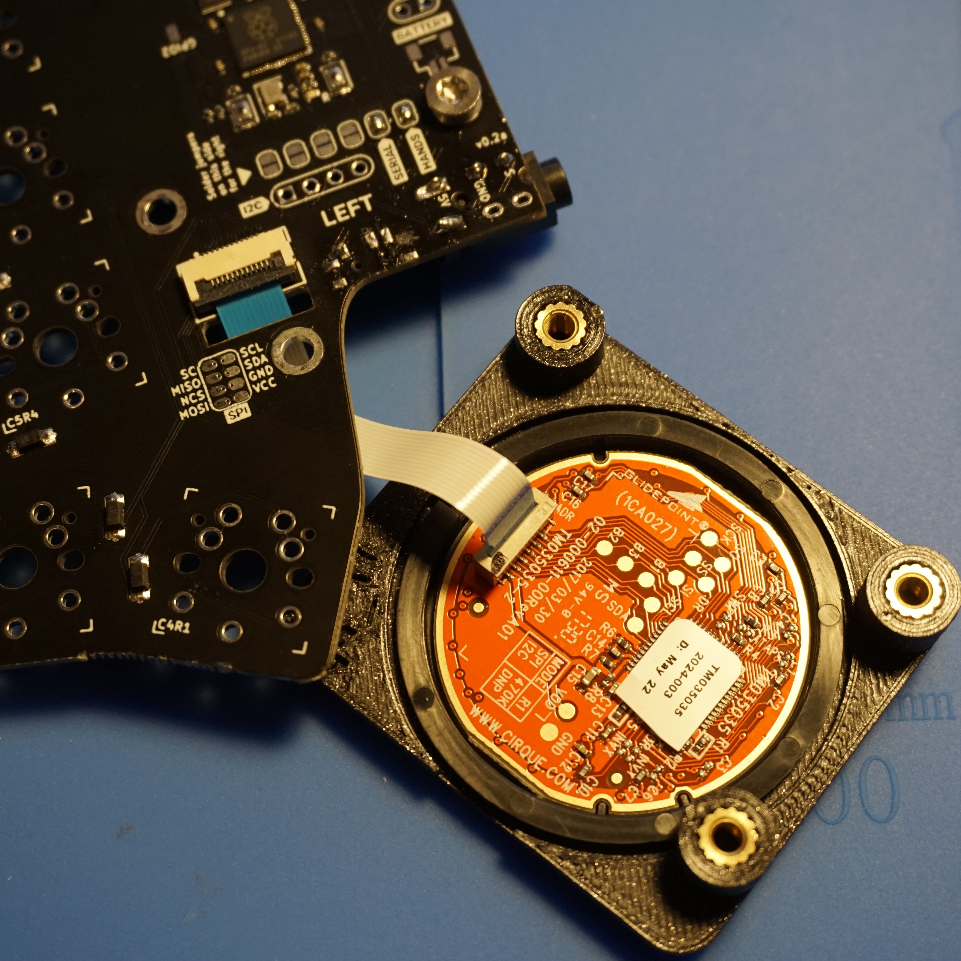

Cables are inserted, next step is to attach the 3D printed assembly so we can attach the trackpad to the pcb.
I didn’t quite manage to do the 90 degrees bend of the cable as in the build guide, but this is good enough for me, for now. Screw in the trackpad to the mounting holes from the bottom side.
Switches
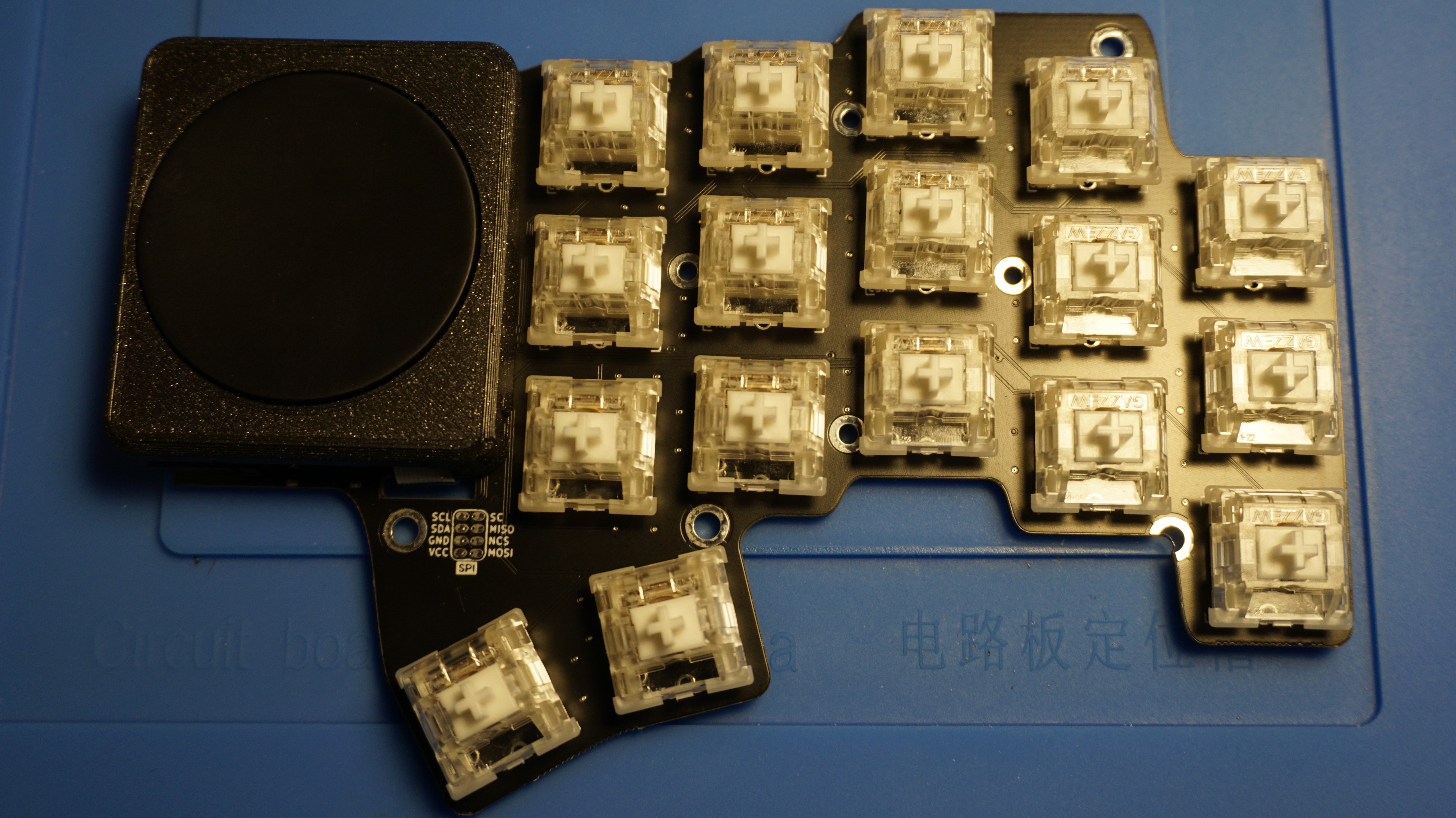
Almost finished! Insert the switches and solder the pins on the bottom side.
I personally prefer MX switches, so I used some Gazzew Boba U4 which I had lying around. Kinda a waste of the clear top I guess, since this board has no RGB.. But since they are the only silent switches I had left and I plan on using this at the office, I decided to use these in this build.
Case
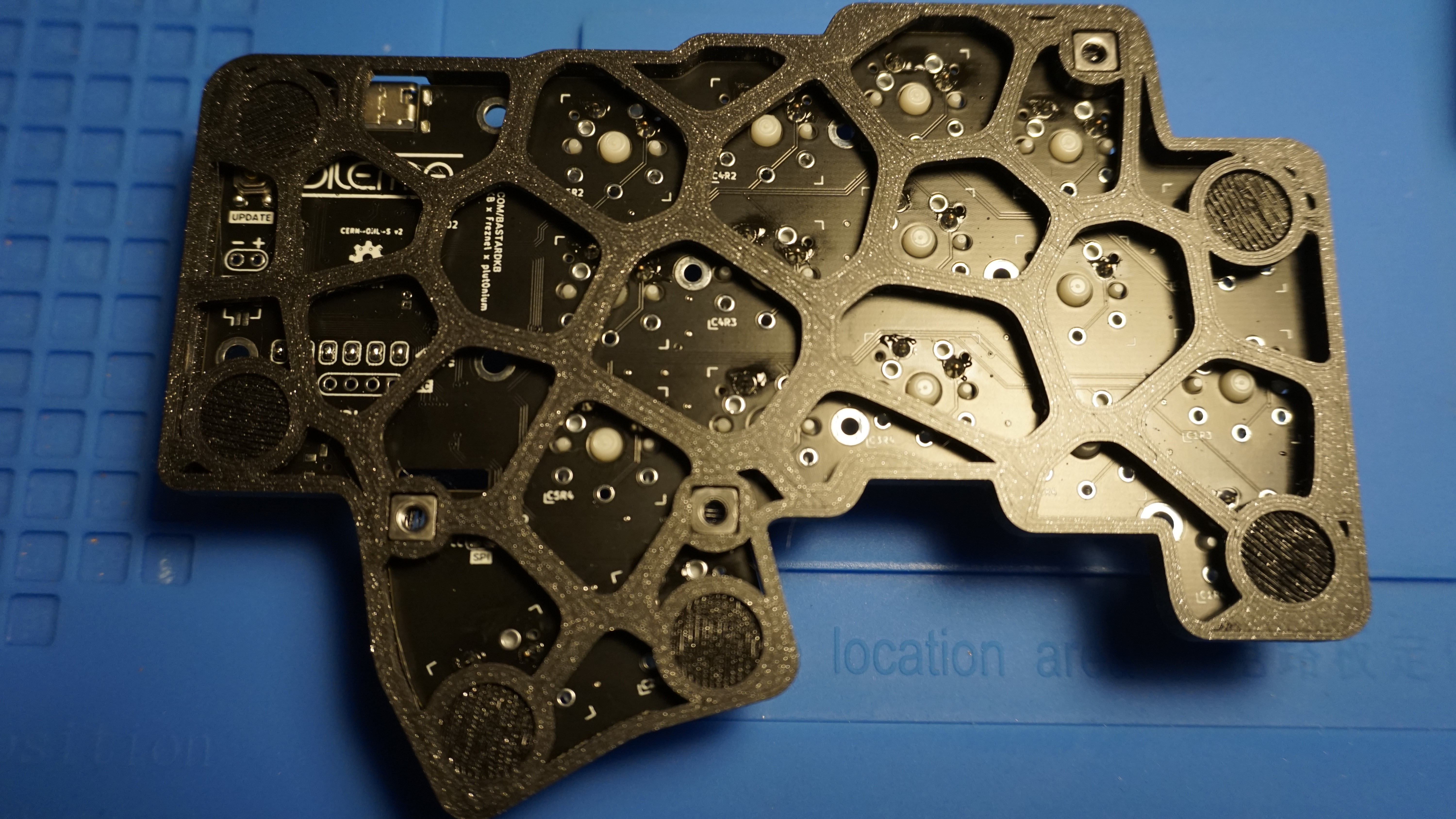
Since I do not have the tenting pucks and tripods yet, I opted for the thin case at this moment. I’ll try the tenting case when I receive the pucks and tripods. I recommend to puncture the screw holes first with a screw and then insert the nut in the square space on the bottom and screw from the top. Tighten those screws. After this stick the anti slip pads on the bottom.
Keycaps
I opted for some leftover NP profile blank keycaps from KBDfans which I also used with my Skeletyl. These are similar to XDA profile, but with more rounded corners.
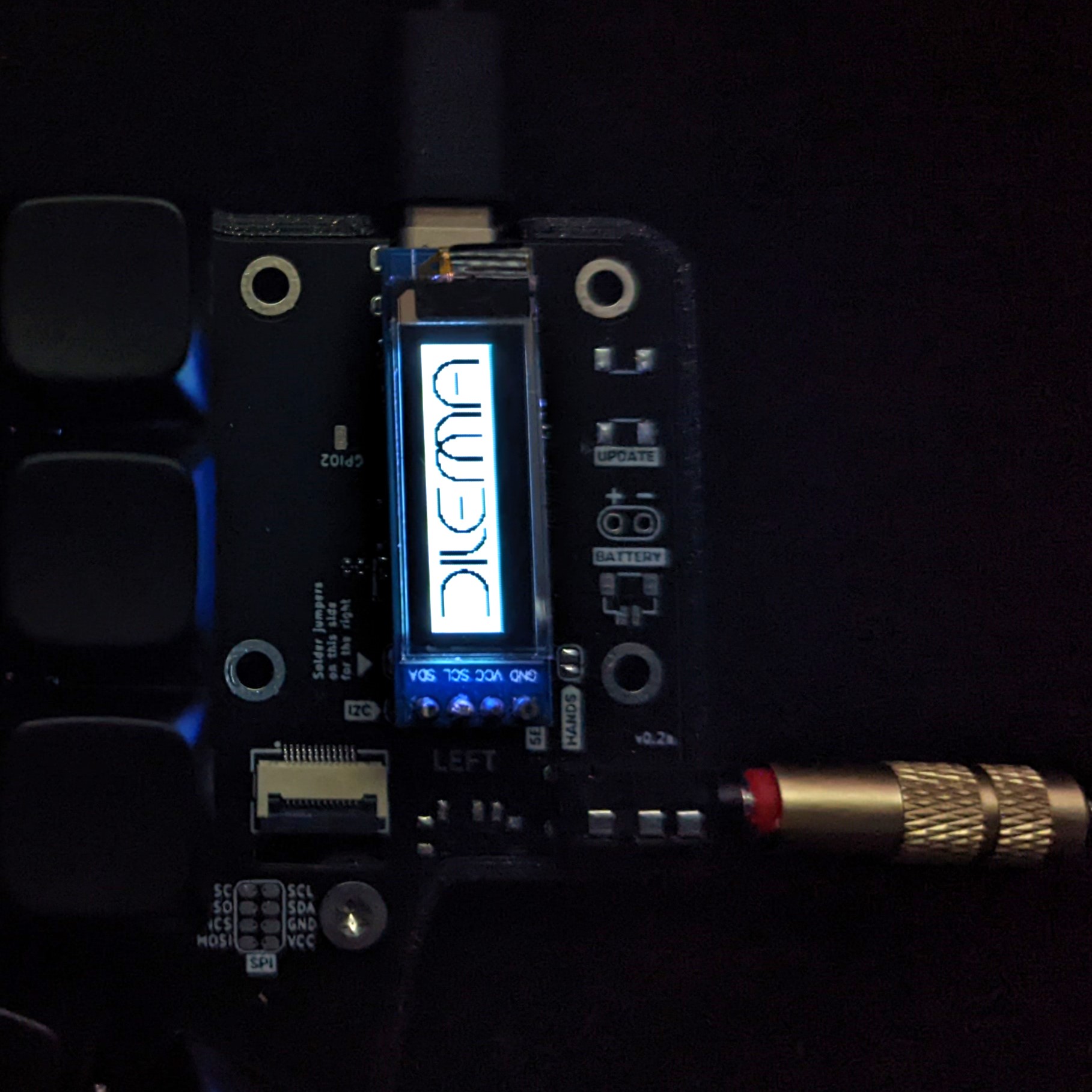
OLED
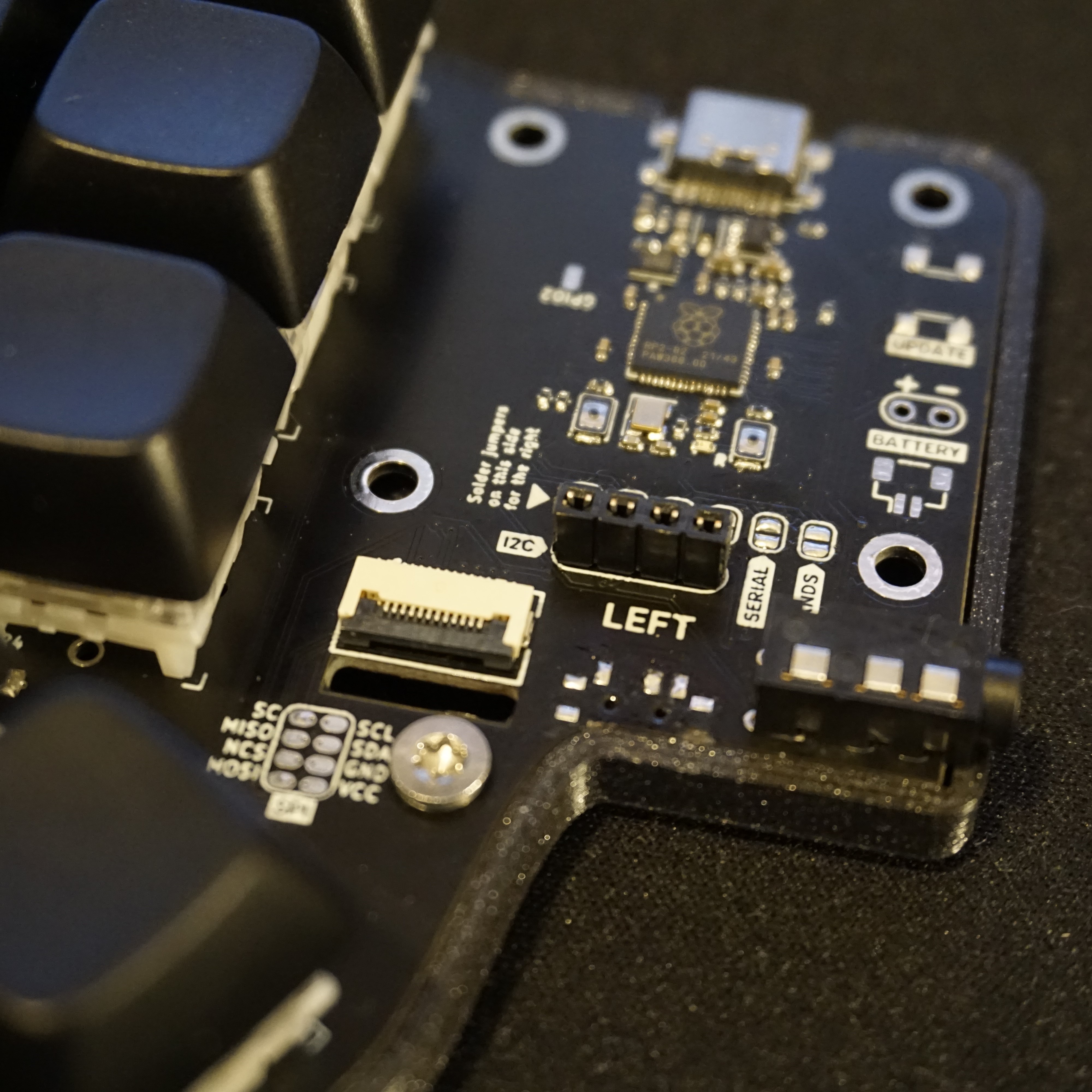
The left half looked rather empty, altho the exposed chip also has a nice feel to it. But to easily accommodate an OLED display I added some sockets. I only had this tiny 128x32 0.91 inch display so I stuck it on here, might try a bigger one later.
Conclusion
I am satisfied with how easy it was doing this build, apart from the mistakes I made by not reading properly, that’s a mistake I make more often. The build time is very fast since the diodes were pre-soldered. There were some issues with the I2C jumpers on the left side with this version, causing the OLED display to not work at first, but that was easily solved by bridging the pads on the other side, just took some time to figure out. This should have already been fixed, the 3D printed case is also being improved, so it is more stable and the reset button is more accessible.
The trackpad is easy to use and accurate, I especially like the circular scroll, nevertheless I do not see myself using it exclusively as a pointing device and ditching the mouse, and I gotta say that I’m not 100% used to using the thumb trackball of the Charybdis either. But seeing as this board is more aimed as a portable board, it works well enough for on the go (using manual mouse layer activation atm).
For the 2 thumbkeys, I only used it for a week, I can live with missing the 3rd thumbkey on the right hand, but I’m having a harder time missing it on the left half. Perhaps it needs some more time and more tinkering with the keymap.
I might try out a wireless version later with nice!nanos, but without trackpad, since that isn’t supported yet. But as it’s a keyboard with portability in mind, having no cables helps.