Cocot46plus build notes
Contents:
Cocot46plus
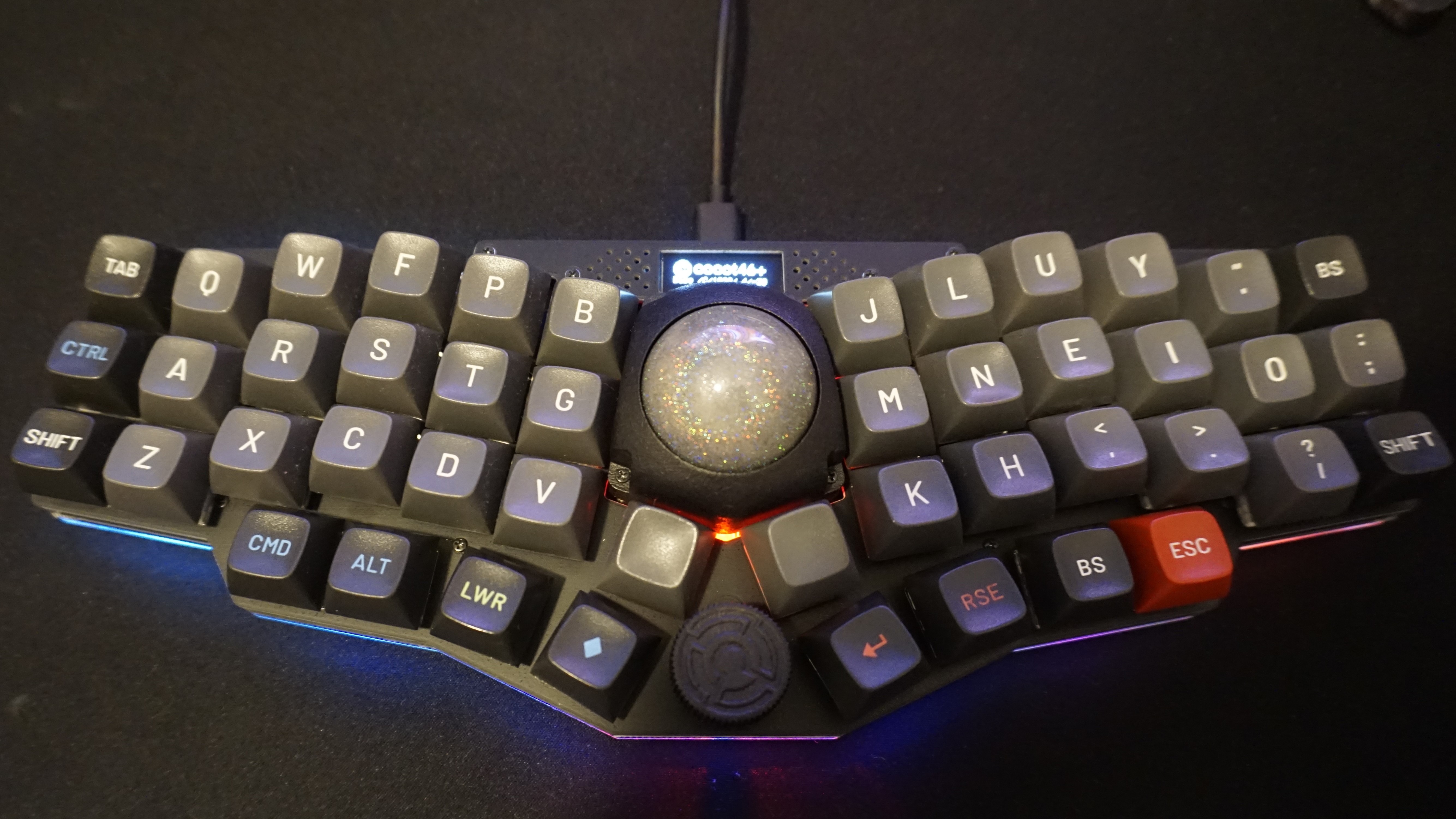
I recently received my Cocot46plus kit, which I got via Charly who lives in Japan (many thanks!), which is a Japanese board designed by aki27 with 46 keys in a Corne-like layout, trackball, OLED indicating layer and trackball status, RGB leds, and rotary encoder, intended for a normal 5V Atmega32u4 Pro Micro. This is the first unibody I built and it seemed very interesting because its form, the dedicated mouse buttons, encoder, and the same 34mm trackball which is also used in the Charybdis.
Parts
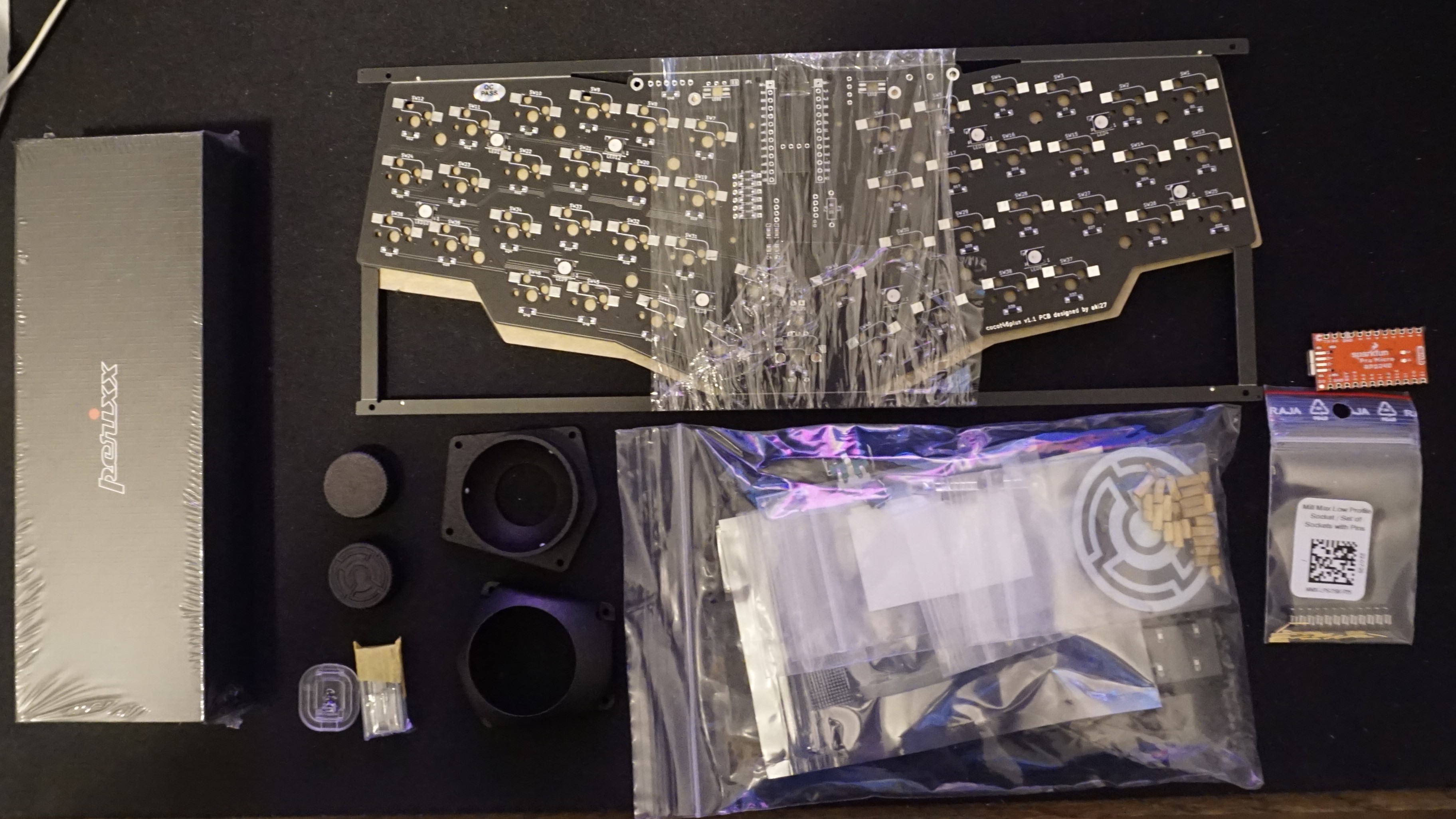

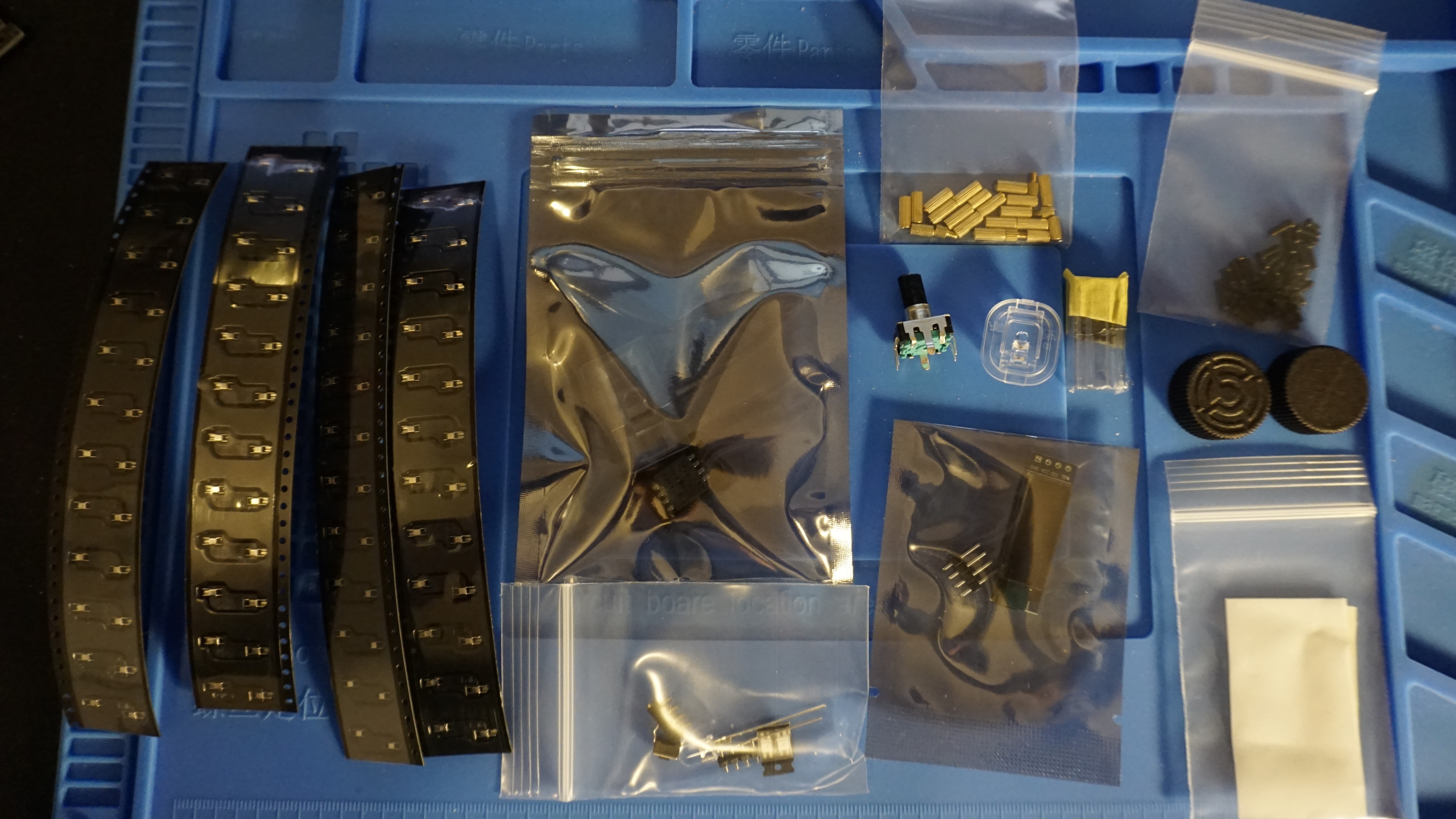

The keyboard kit contained the following:
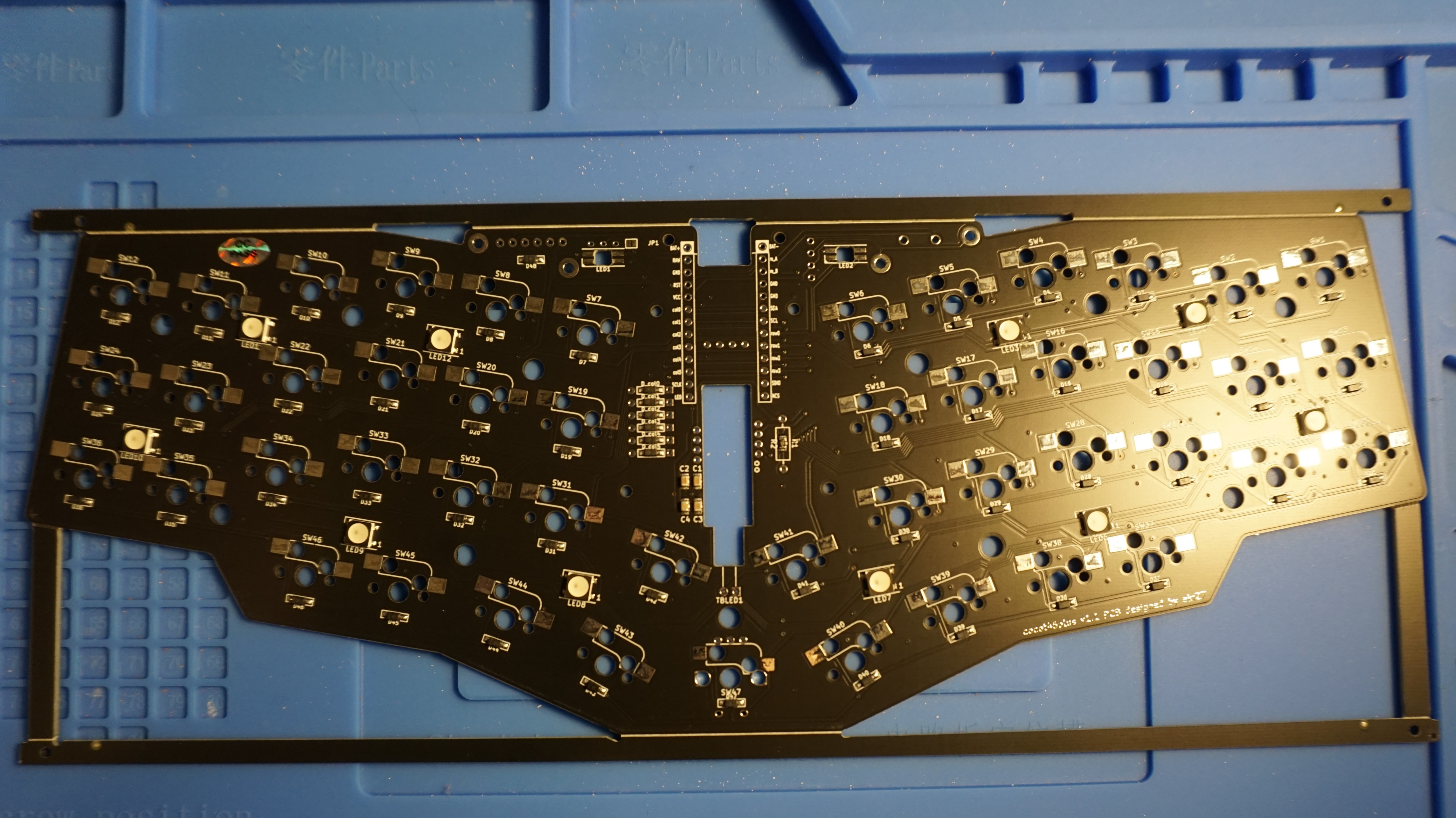
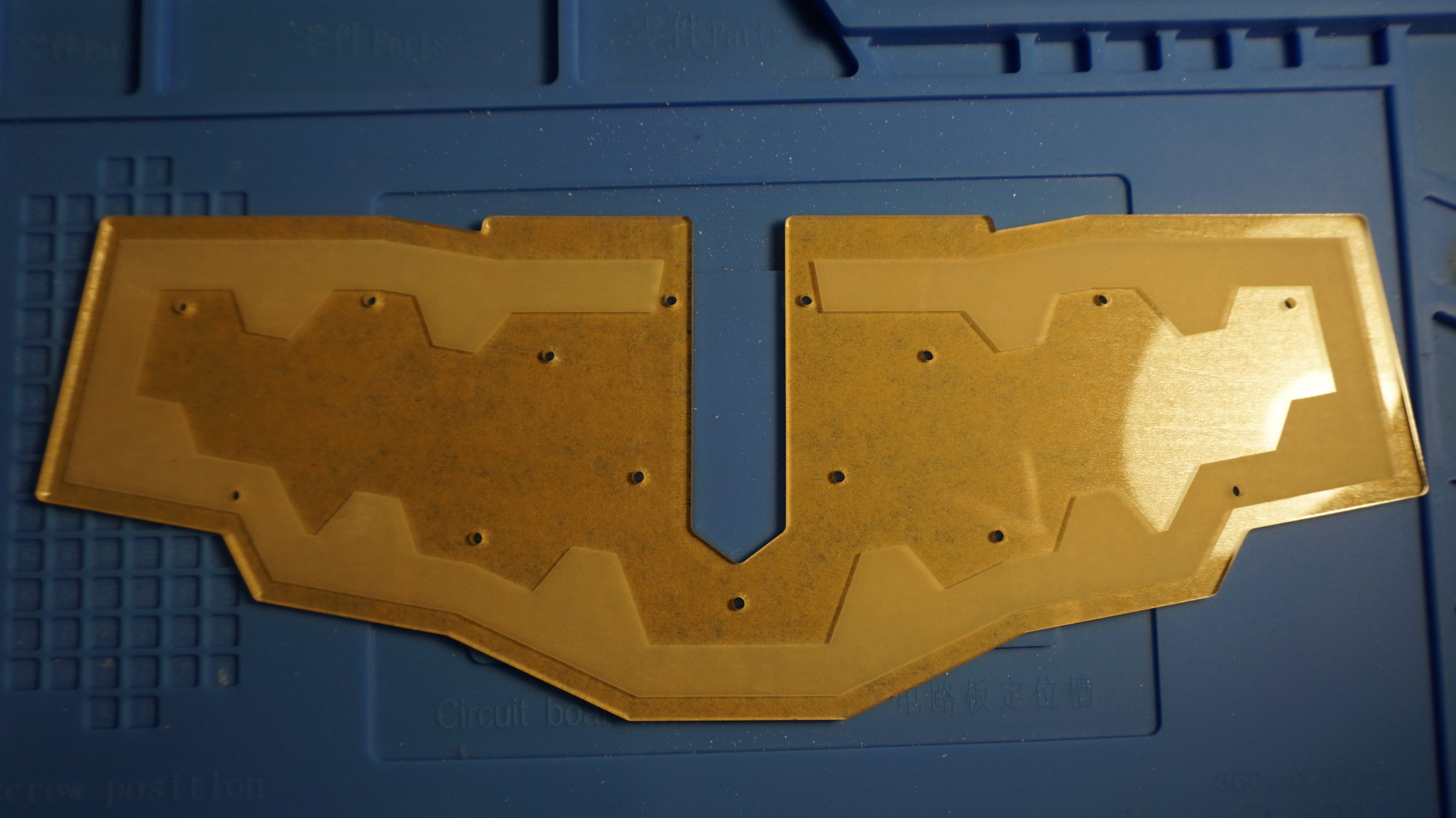
- PCB
- Acrylic bottom plate
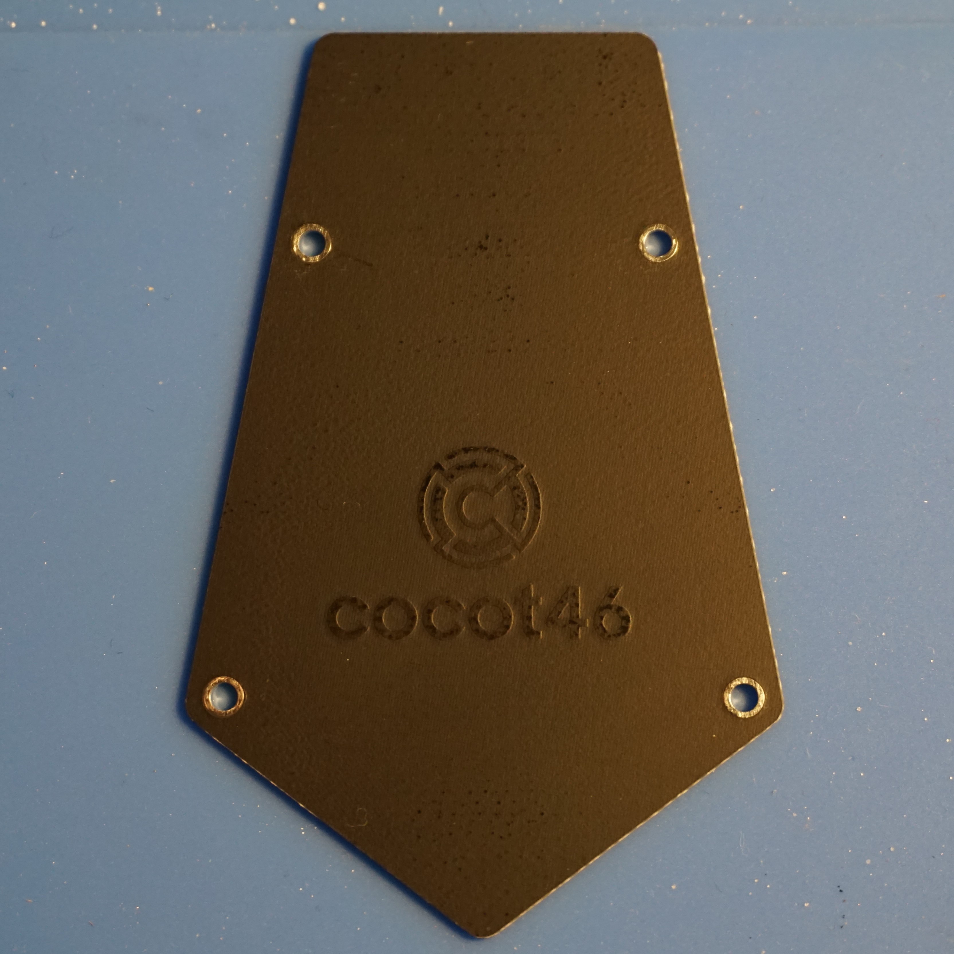
- FR4 bottom MCU cover
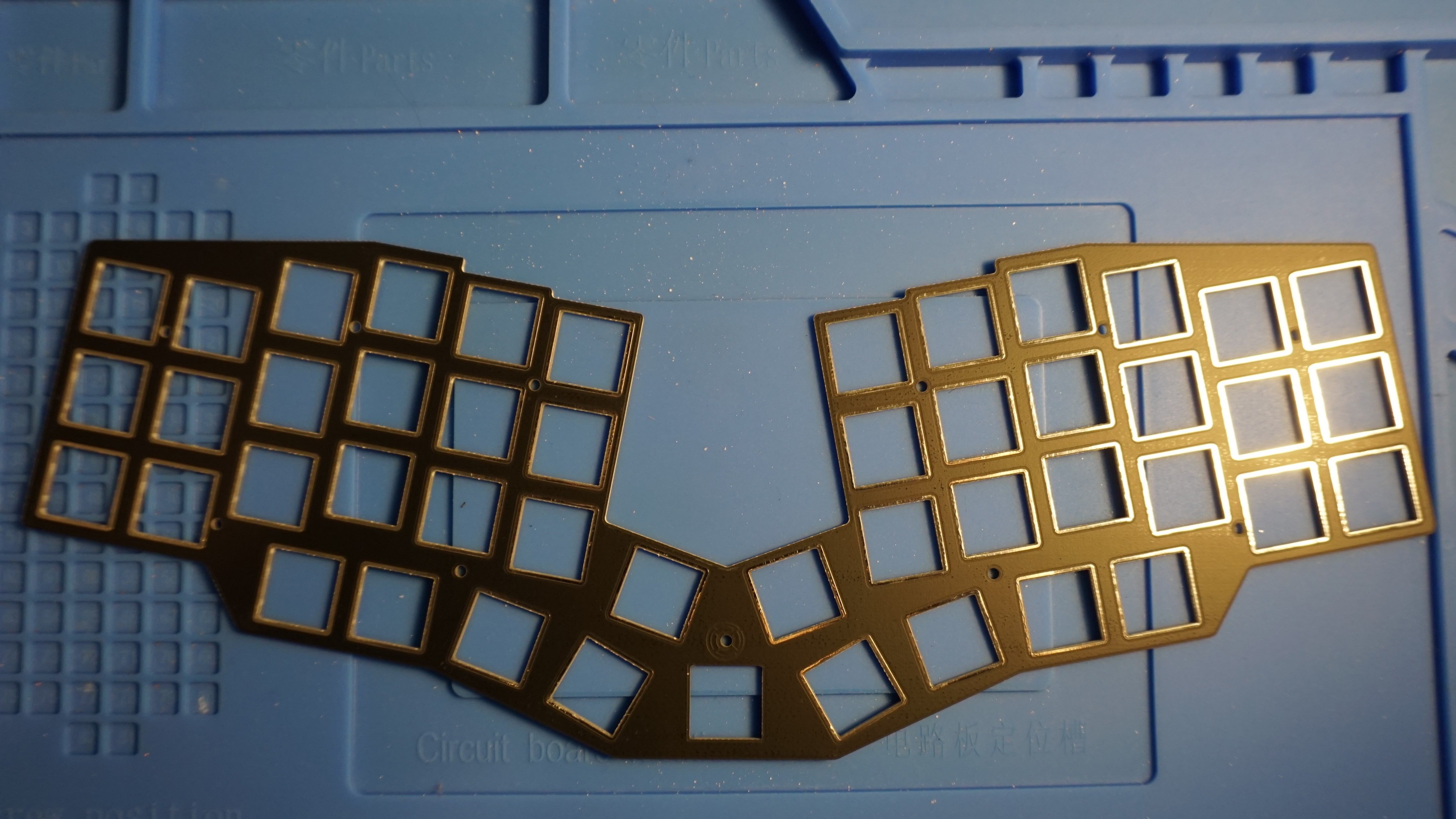
- FR4 switch plate
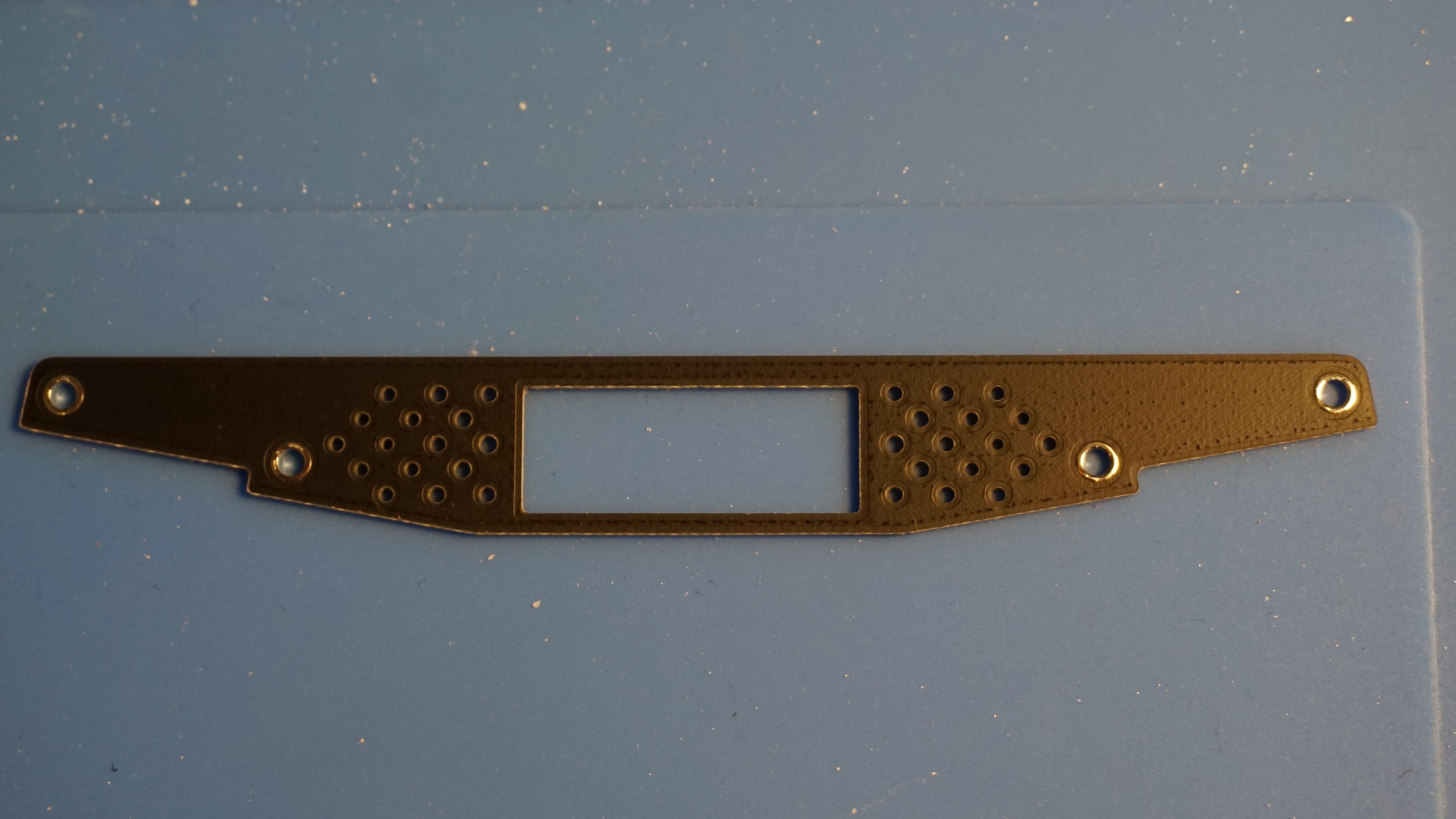
- FR4 OLED cover plate
- Different sizes screws and standoffs
- Kailh MX hotswap sockets
- Mouse sensor (ADNS-5050) and lens piece (I actually received these twice, not sure if that is intended..)
- Trackball holder (bottom and top)
- Red LED for the mouse sensor
- OLED display
- Reset button
- Rotary encoder
- 2 SK6812MINI-E RGB LEDs
- Anti slip pads
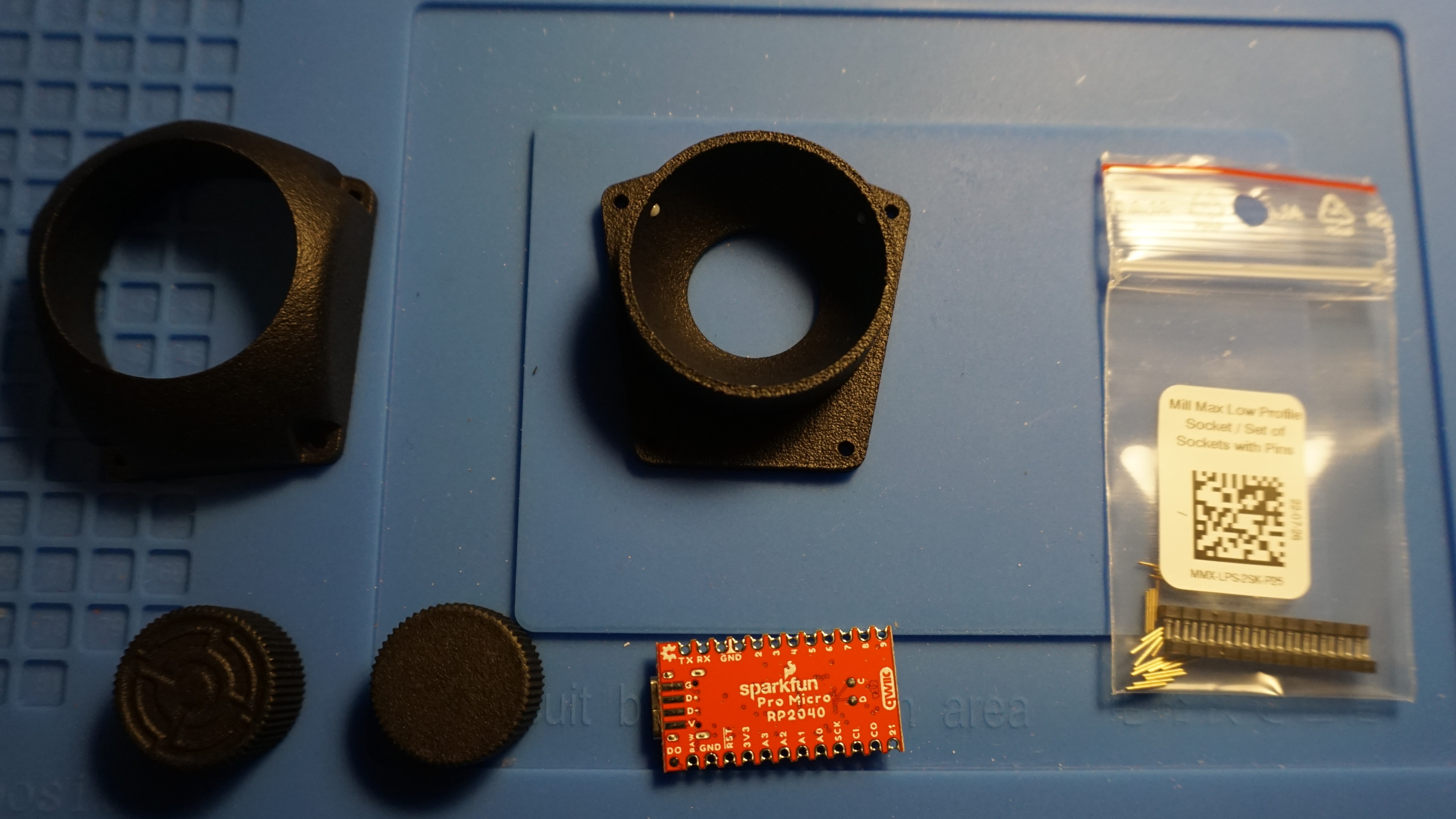
Besides the kits content I prepared:
- 34mm trackballs (4-pack)
- 3D printed rotary encoder knobs (also from aki27)
- Mill Max Low Profile Sockets and pins
- Sparkfun Pro Micro RP2040
- Kailh Box Whites
- MT3 Susuwatari keycaps
- Lens holder
Build notes
I mainly followed the official English build guide and I’ll take notes here on some deviated paths I took.
Presoldered parts
The diodes and underglow RGB LEDs come presoldered, this saves some solder time. I believe the Kailh hot swap sockets can also be pre-soldered by JLCPCB for example, which would have saved even more time, but I am not sure how much that would increase the price. Besides the sockets there isn’t much to solder anyway, so it’s no big deal.
RGB Indicator LEDs
The board has 2 RGB LEDs pointed up, those are used as layer indicators and thus will change color when changing layer.
Trackball sensor
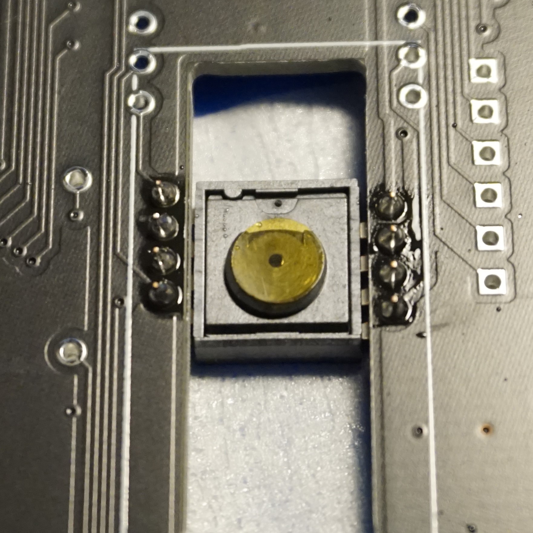
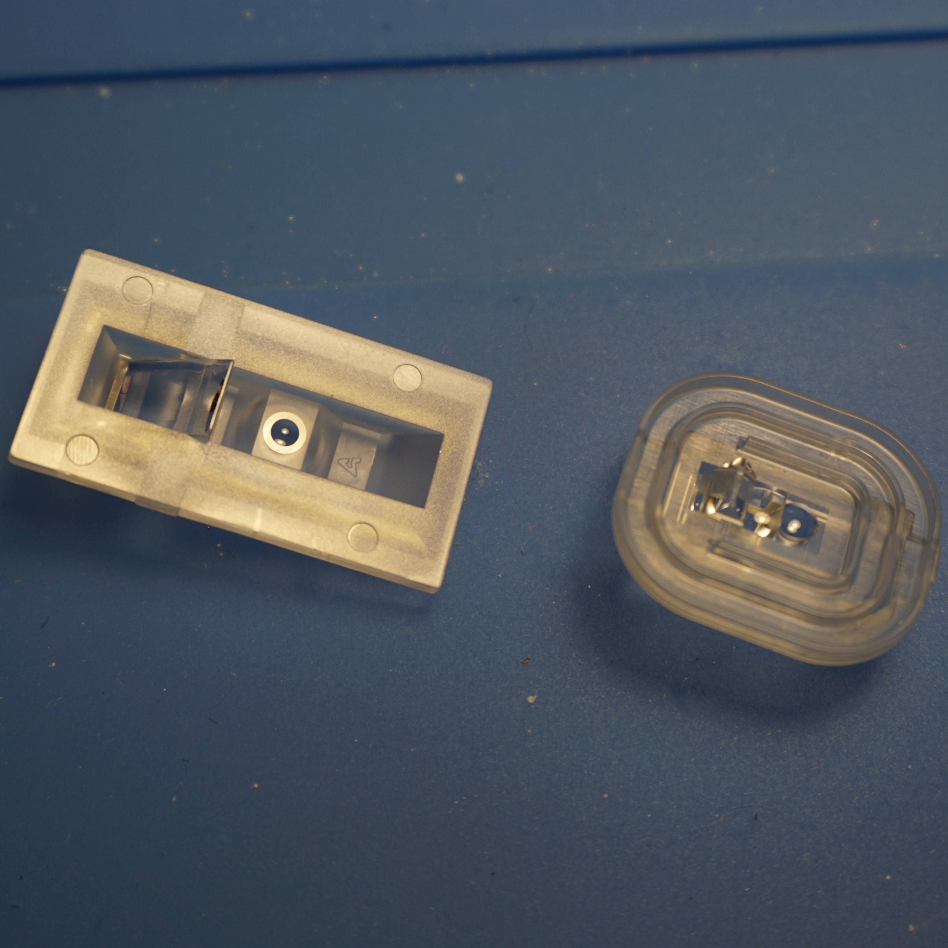
Next I soldered the trackball sensor. I actually received two sensors and two different lenses, but I am not sure why. The second lens was also of a different shape and didn’t fit anyway. Perhaps a kitting mistake?
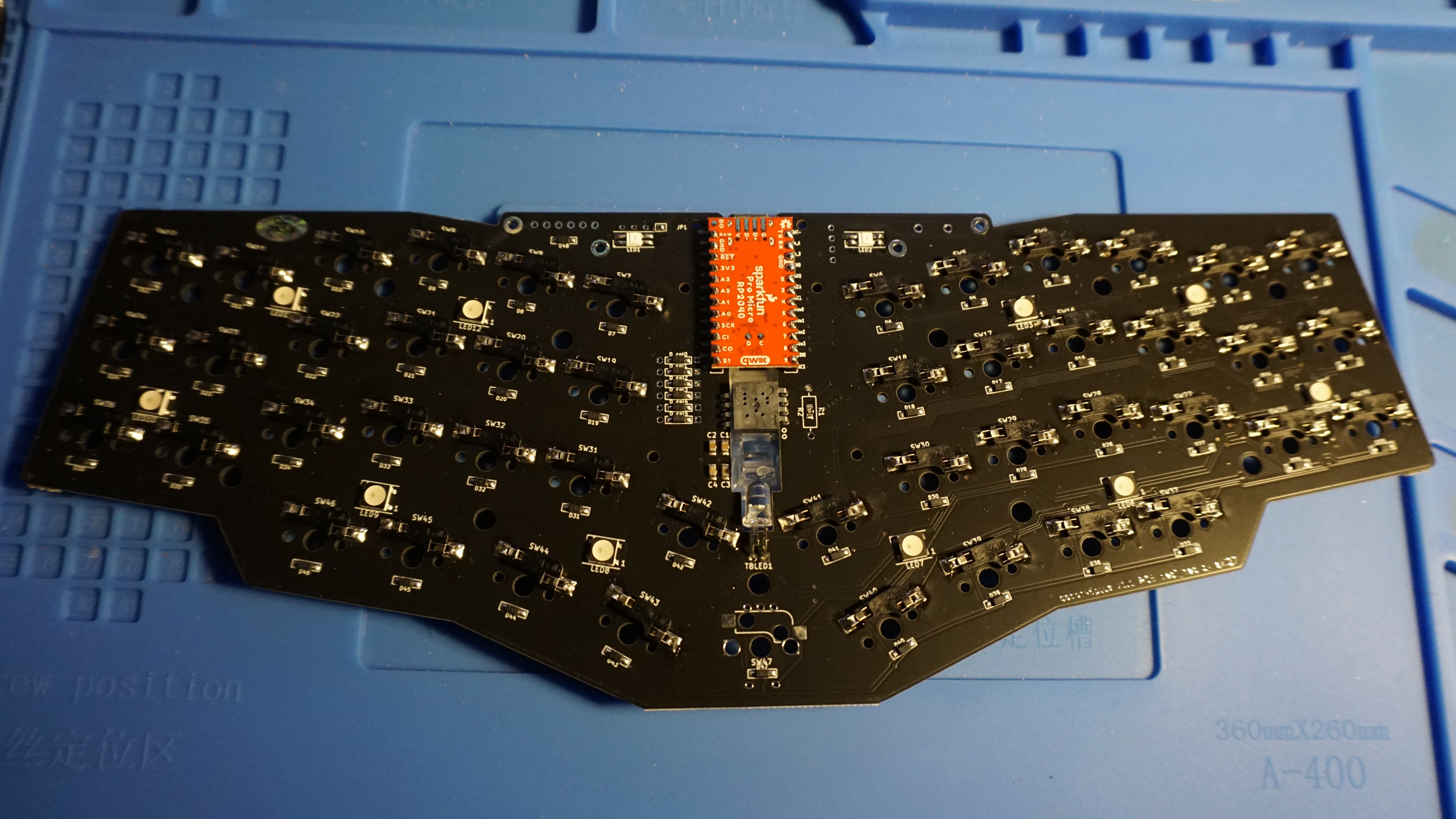
Mill Max hot swap sockets and RP2040
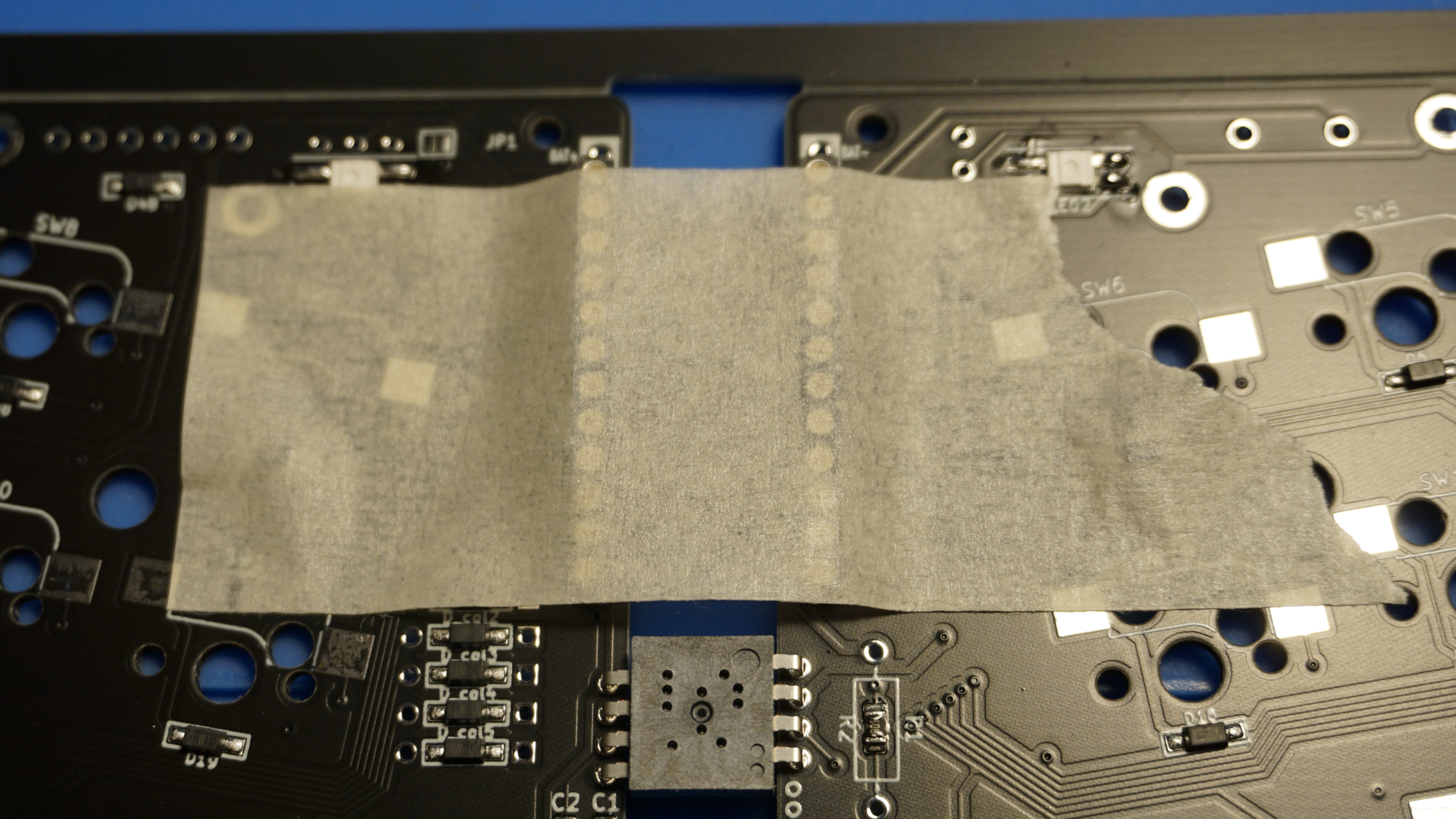
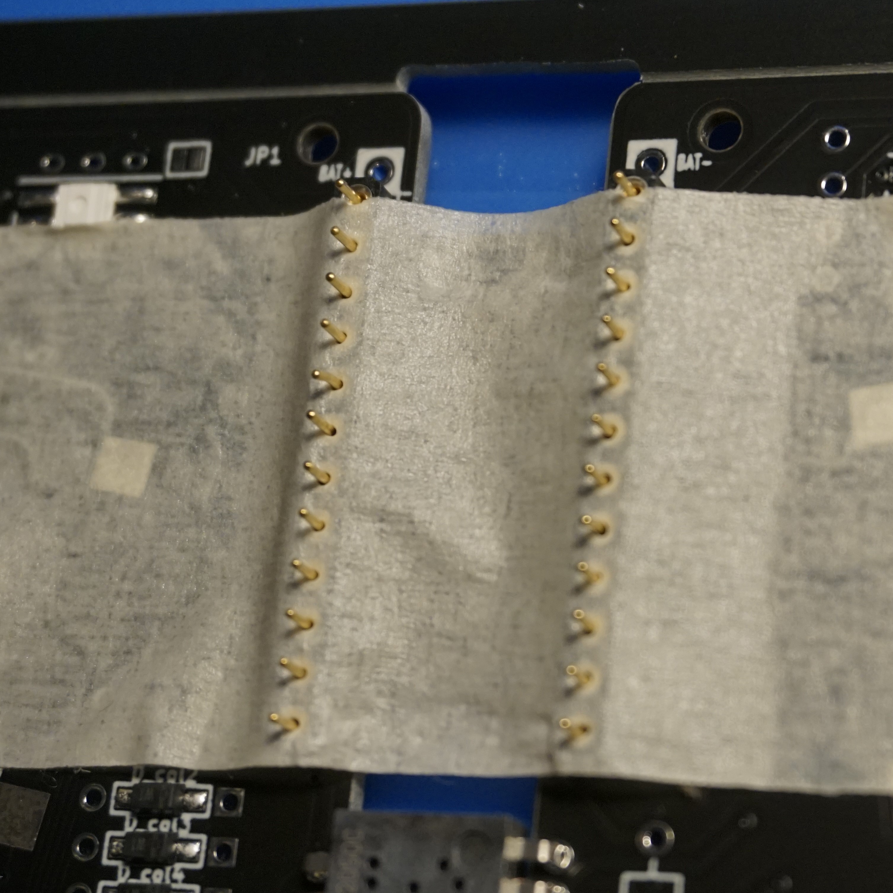
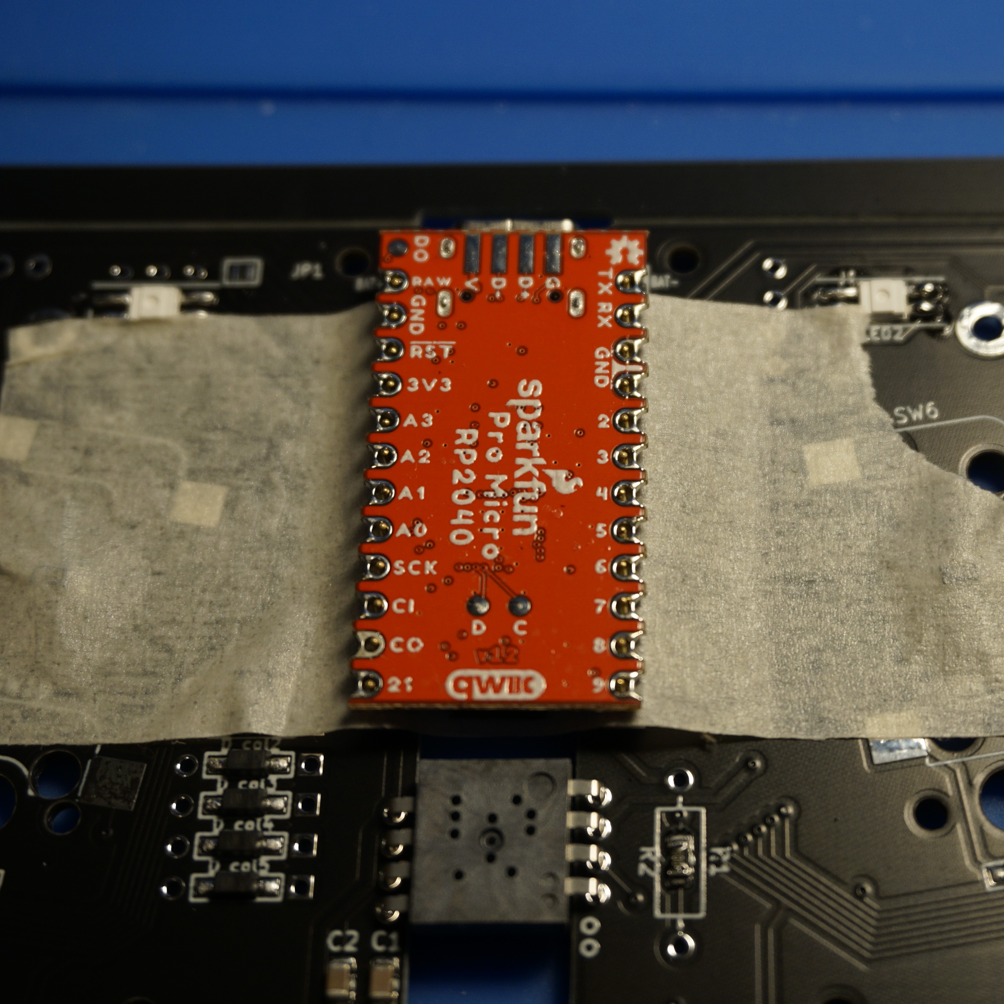
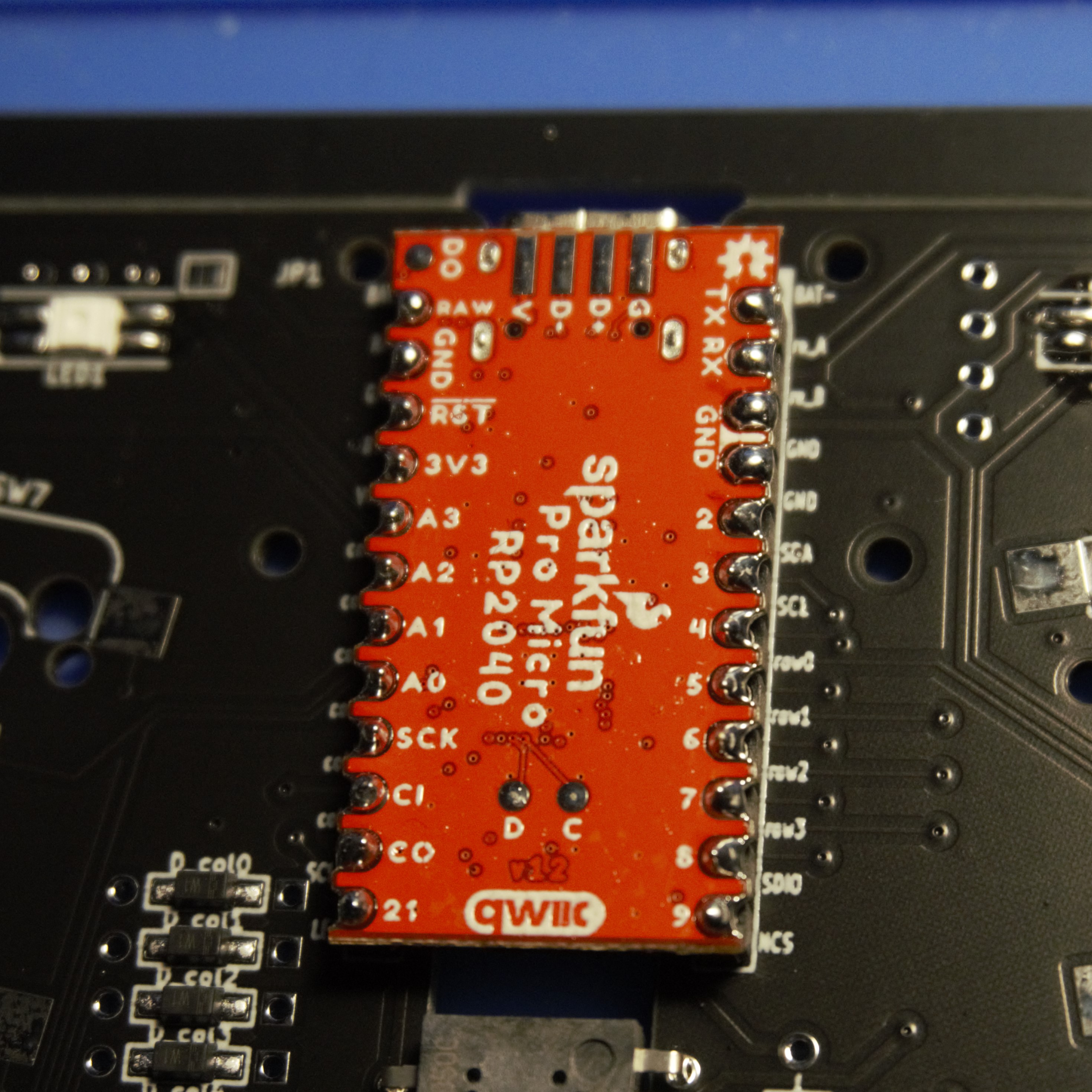
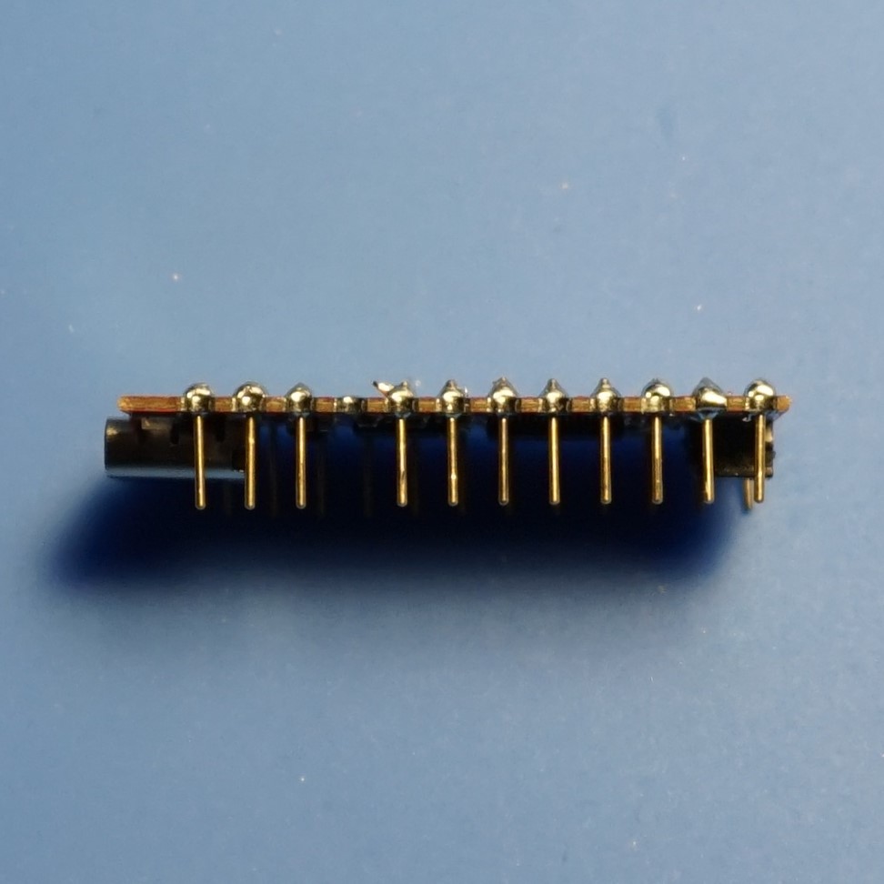
In the official build guide they use spring loaded header pins, which seems to be the more popular choice in the Japanese keyboard world. However, these are near impossible to get in Europe. I have used them in the past when I bought them from Keycapsss, but they are out of stock since a while with no indication when they will get back in stock. Besides the availability, the PCB has to support them, and there doesn’t really seem to be a consensus on the mcu pin hole size here.
Because of that I opted for choosing an alternative, which seems to be the standard in the West, Mill Max sockets.
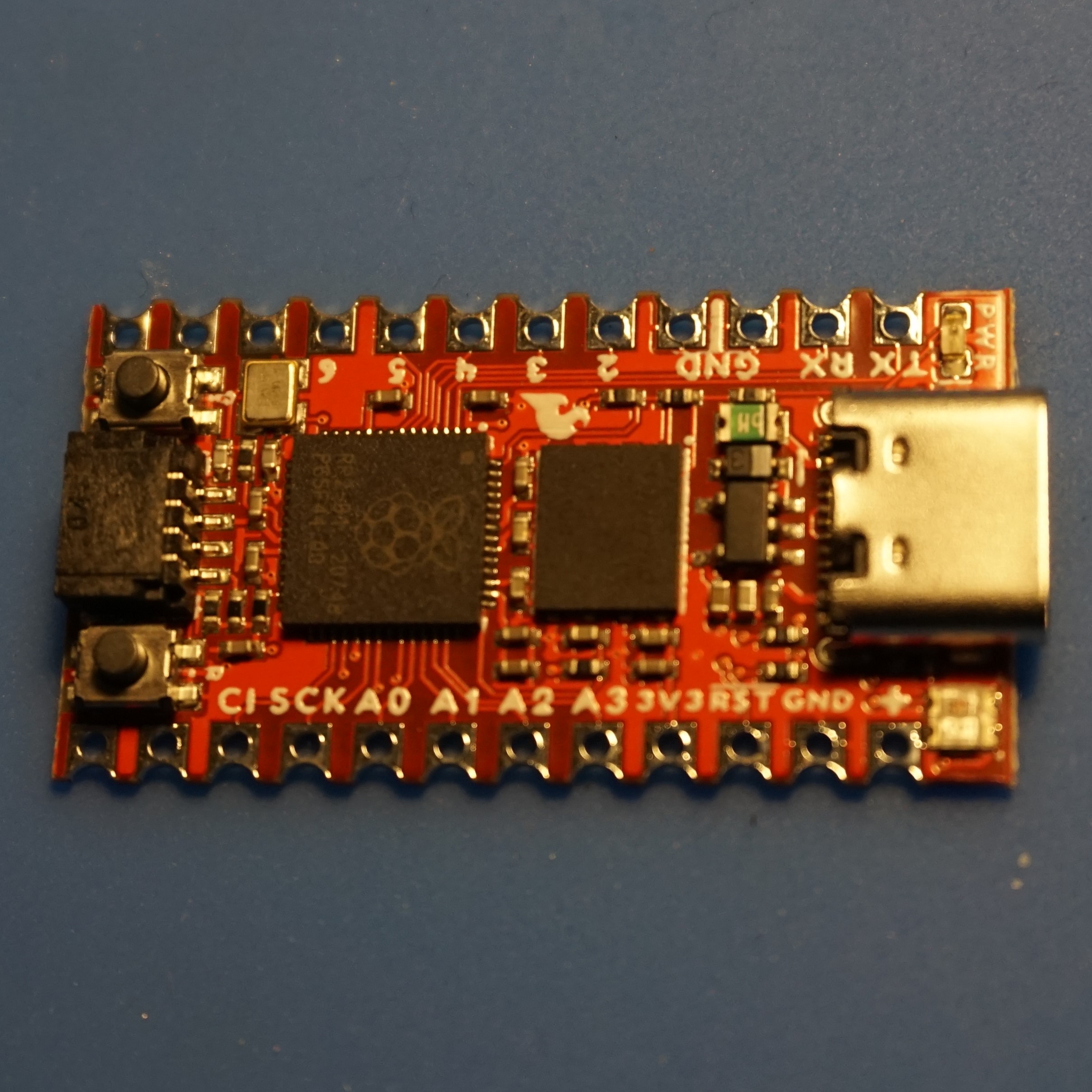
The keyboard is built for an Atmega32u4 microcontroller. Since those are getting harder to get and more expensive, due to the chip shortage. Plus I keep running into storage issues with those, I wanted to upgrade to a RP2040 microcontroller. I have some Sparkfuns and Splinkies, but since this board does not use the bottom row of pins which are present on the Splinky, I opted for the Sparkfun.
LEDs
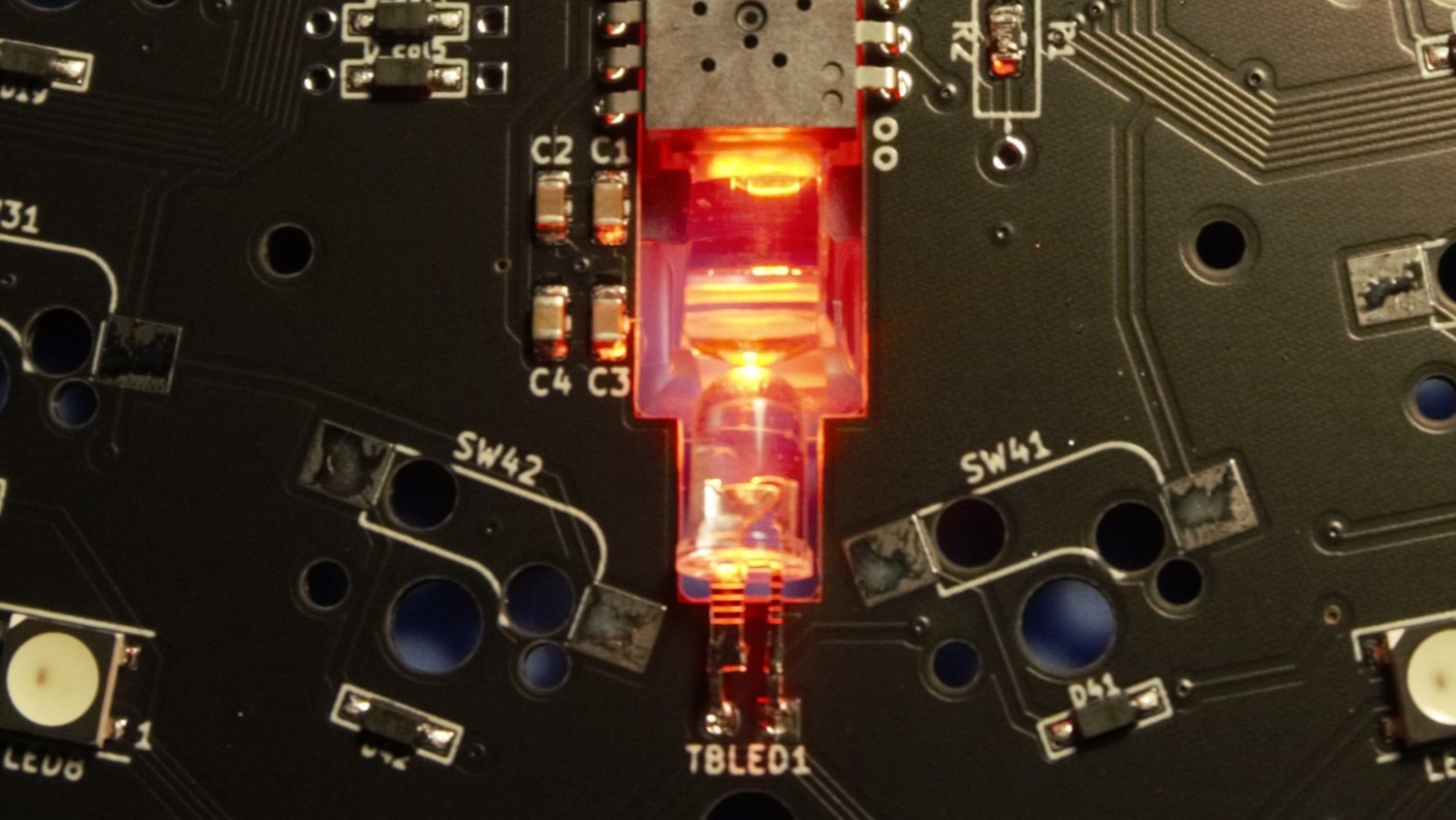
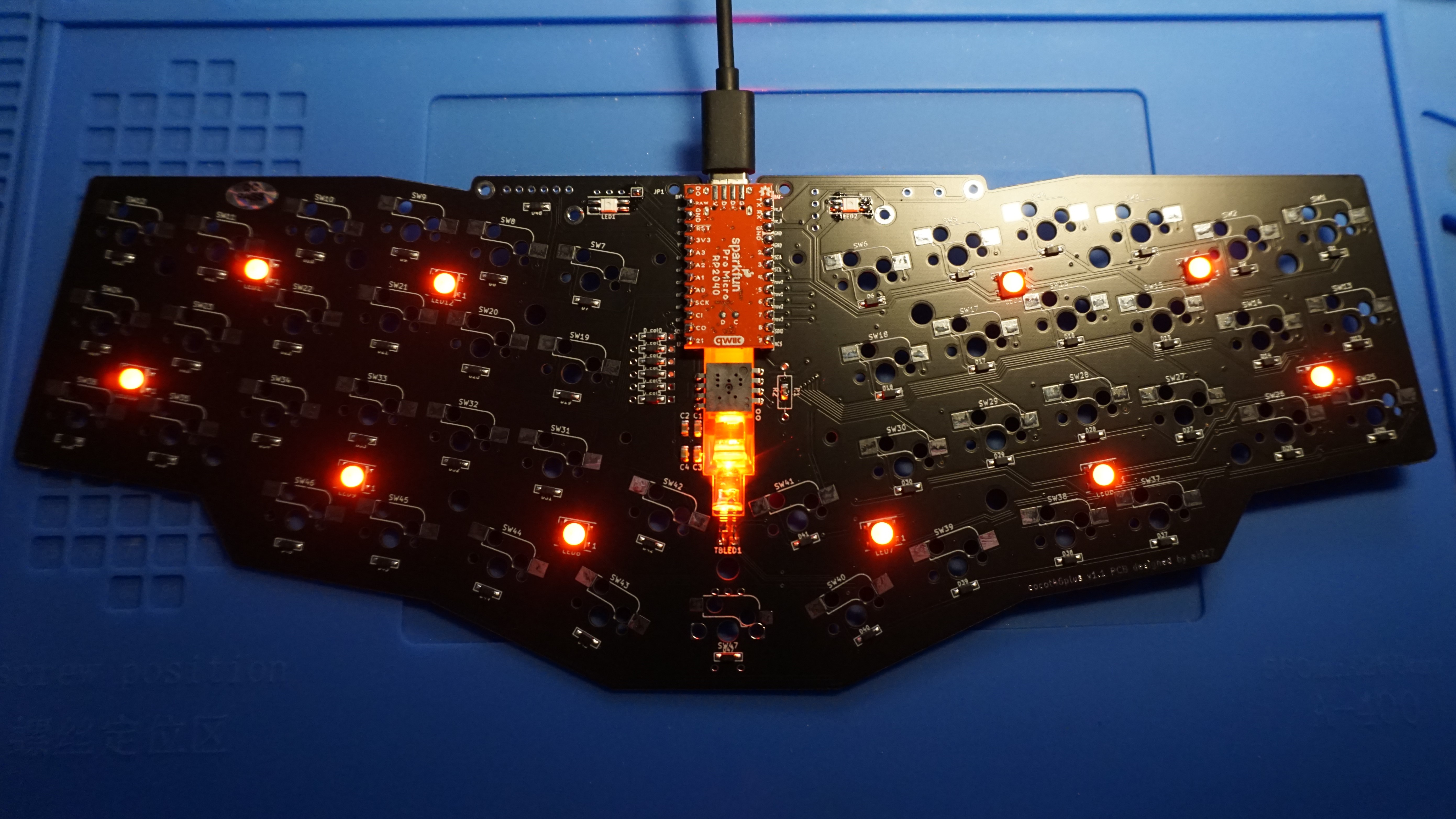
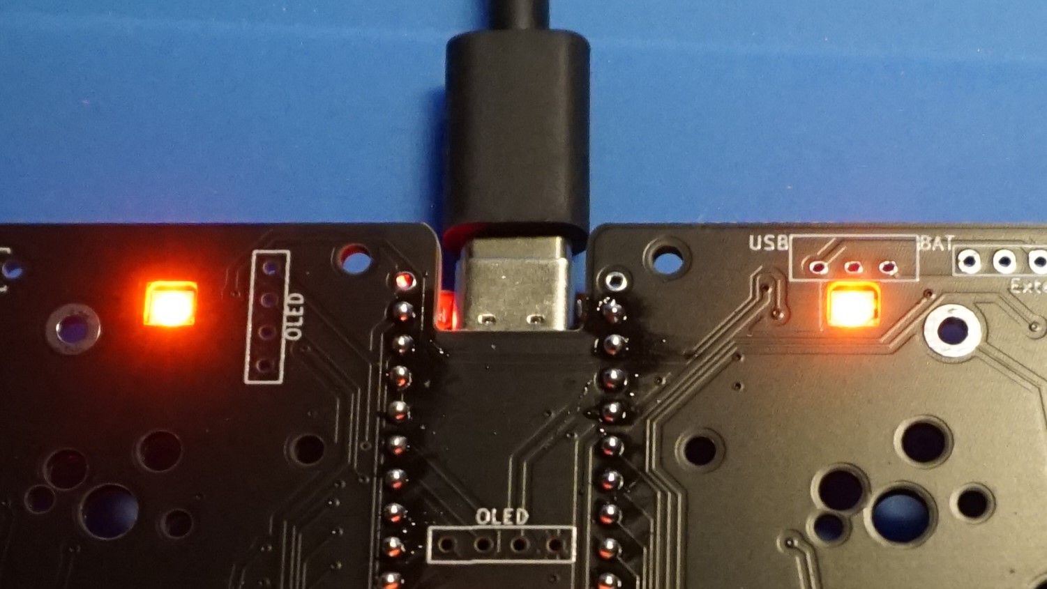
Soldered the LED for the sensor and checked if all LEDs are functional by plugging in the USB C cable.
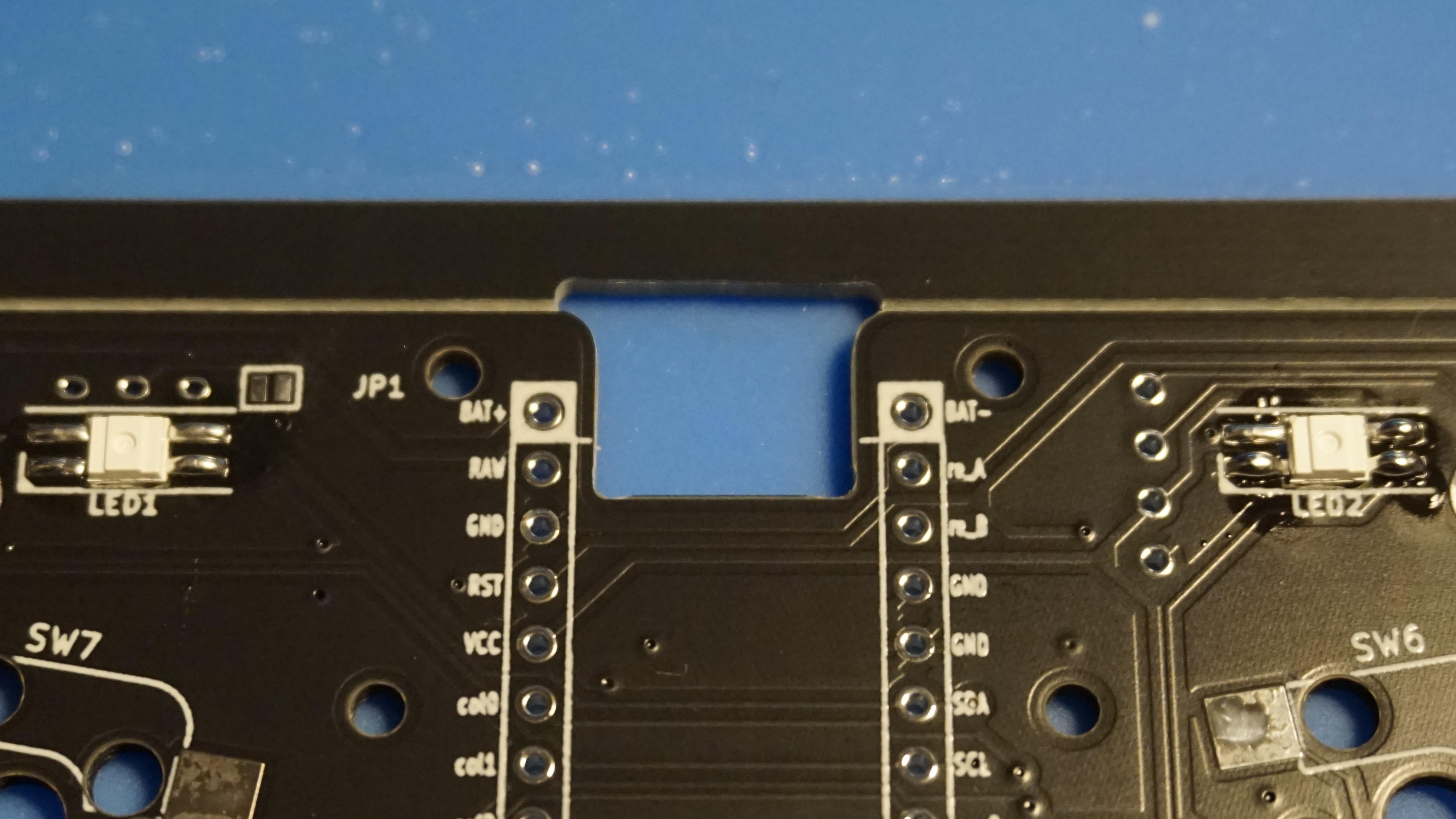
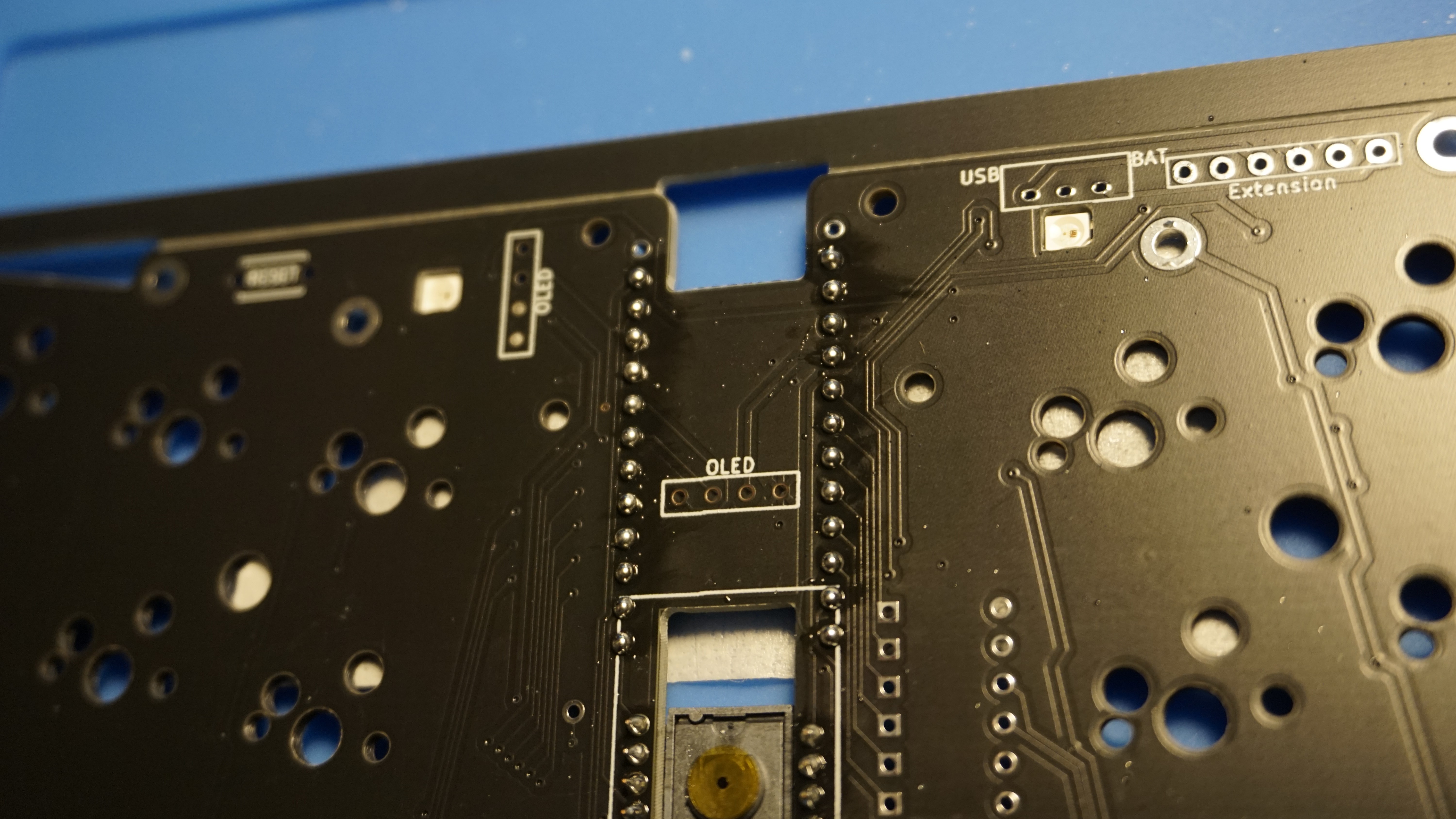
OLED socket and reset button
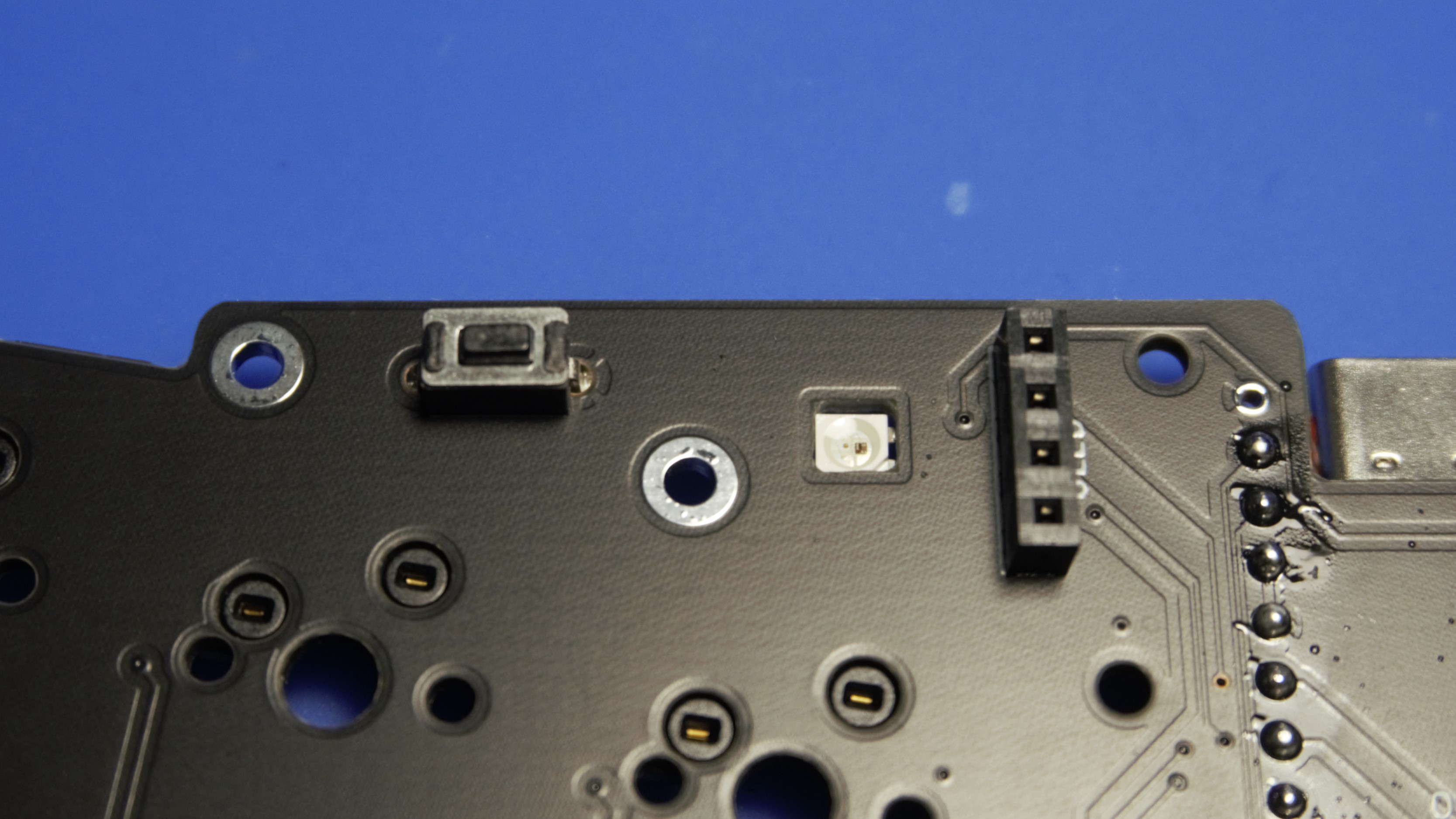
Next step is to solder the socket for the OLED display and the reset button.
Kailh hot swap sockets
Solder all the hot swap sockets. Since the bottom center will house a rotary encoder, no need to solder a hot swap socket there.
Rotary encoder
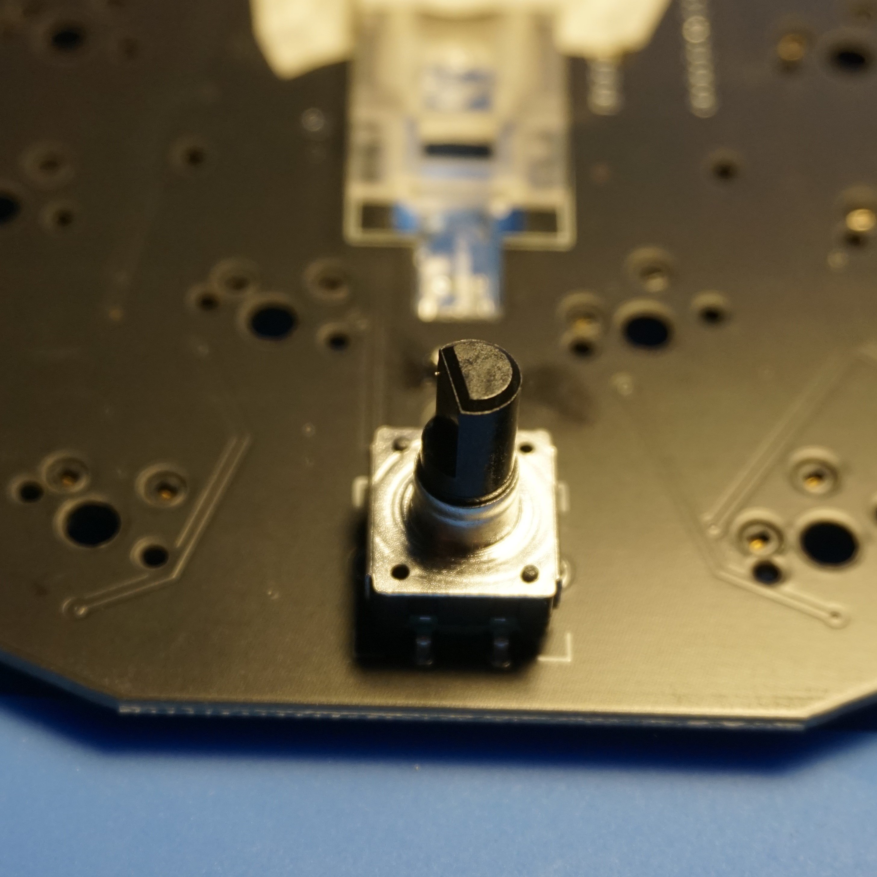
Fit in the rotary encoder and solder it.
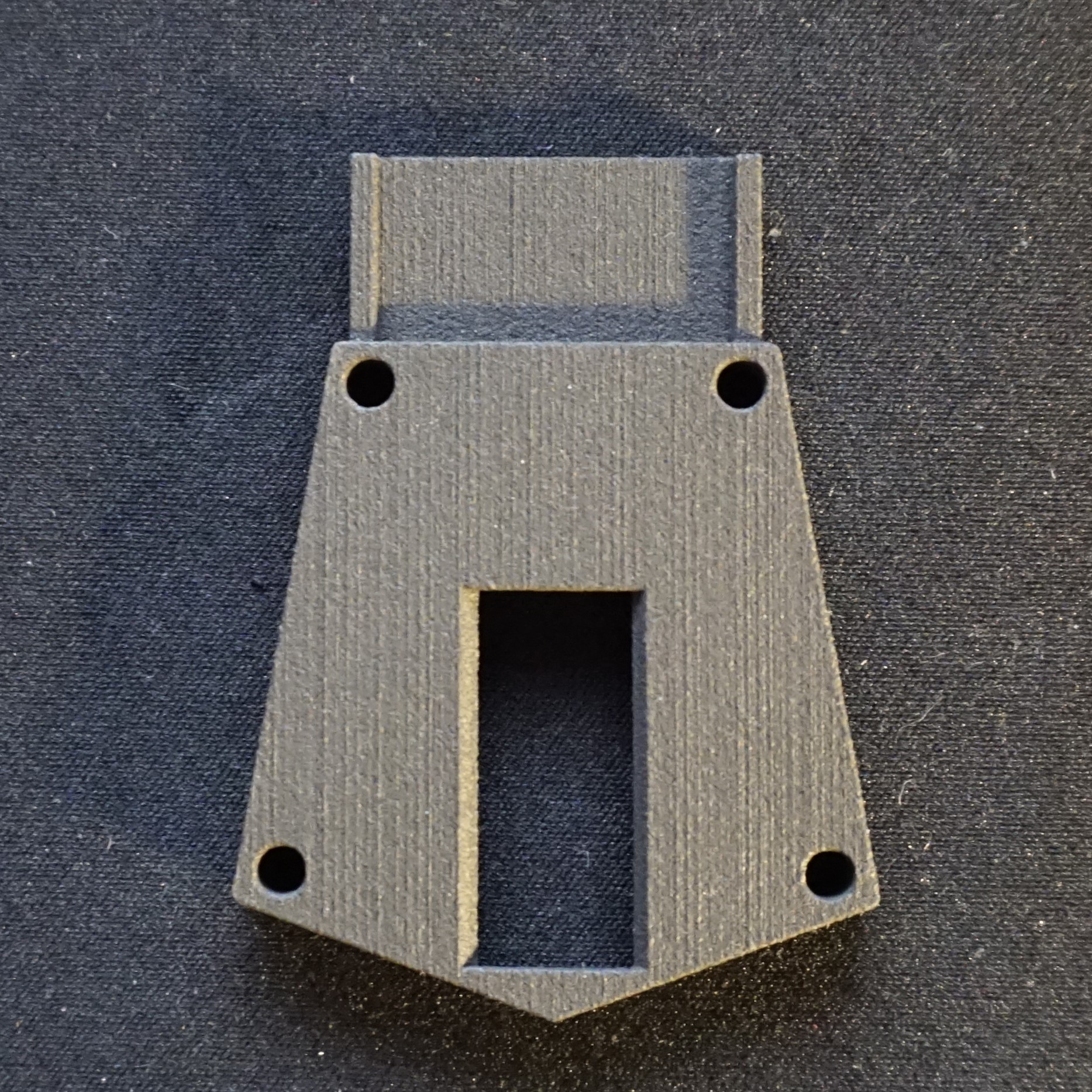
Lens holder

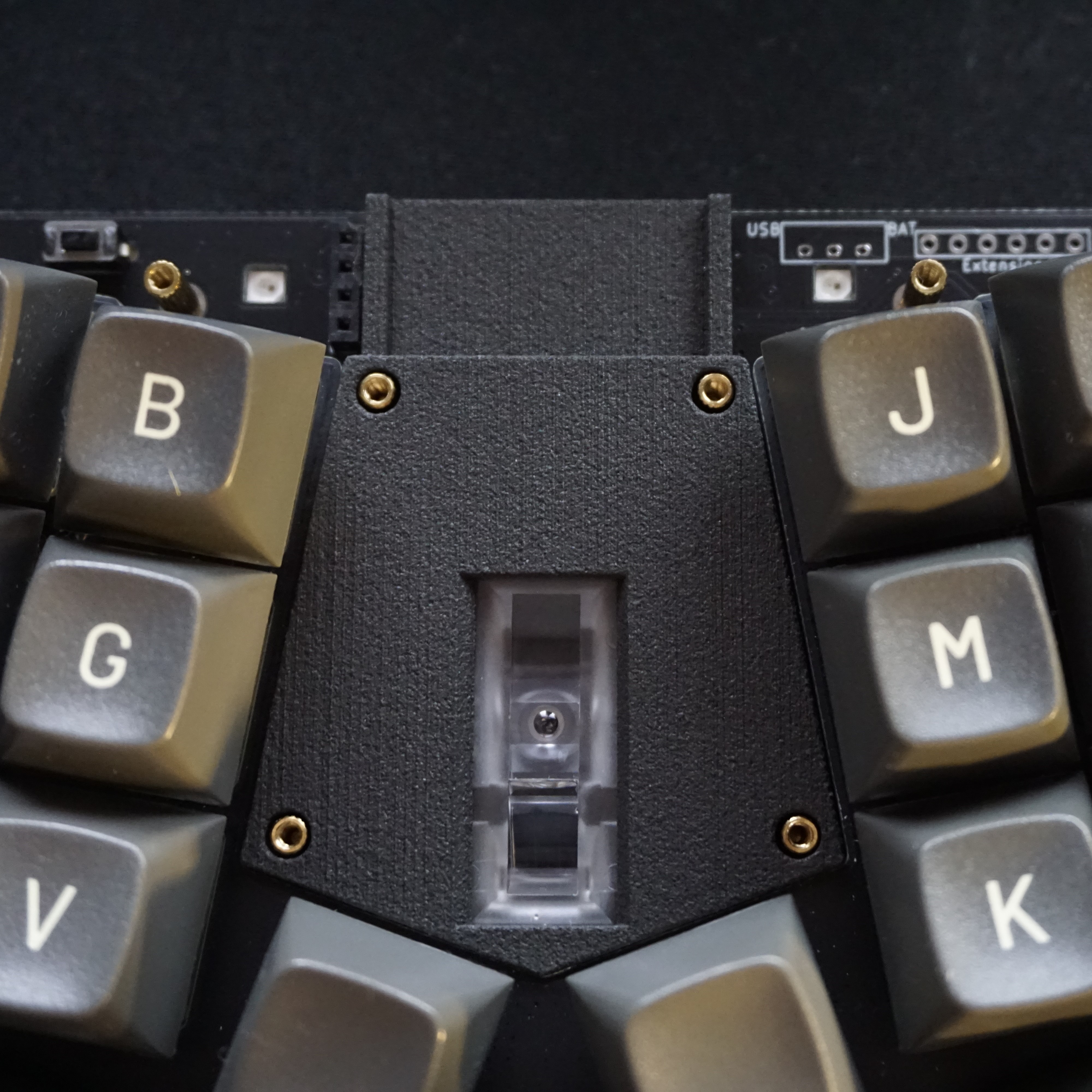
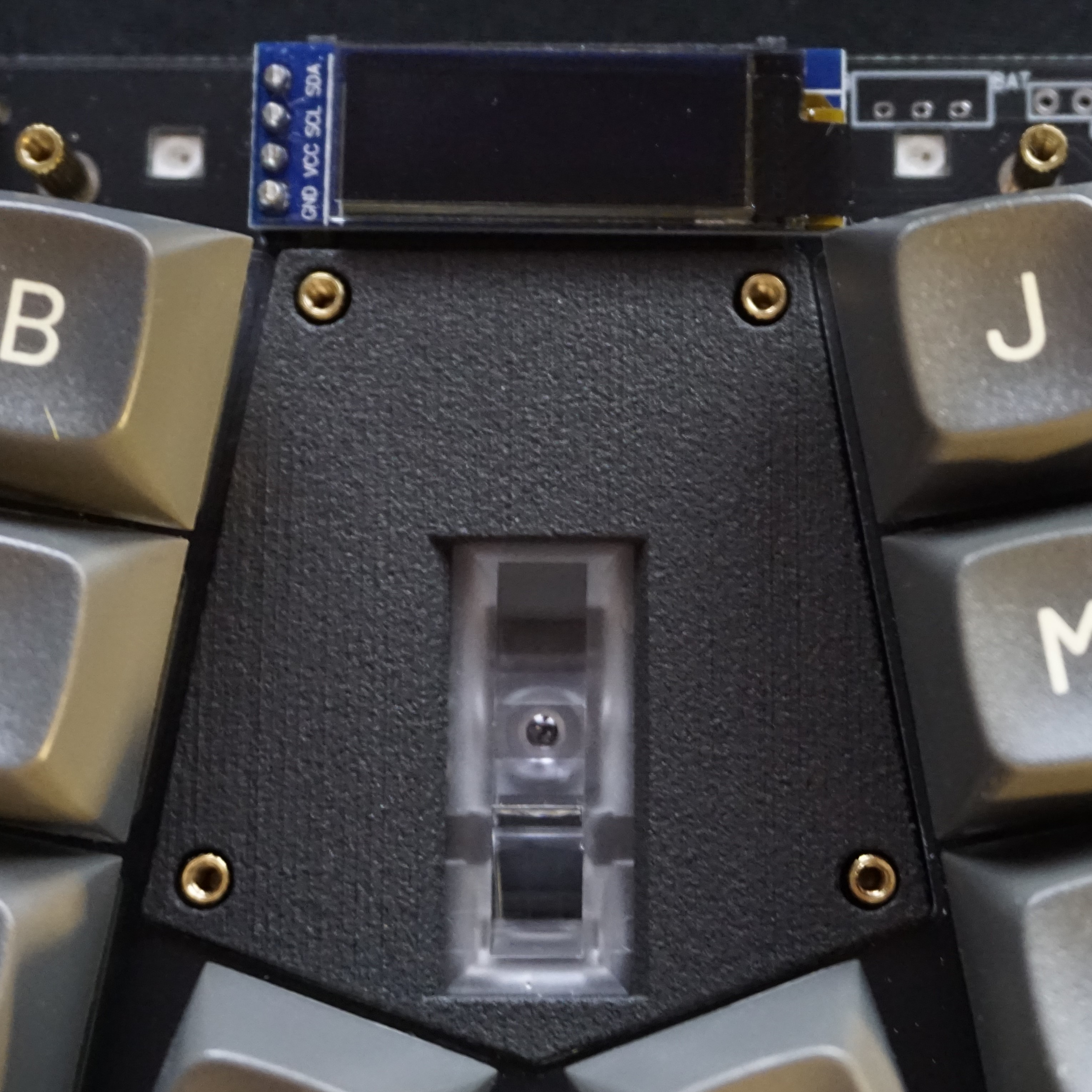
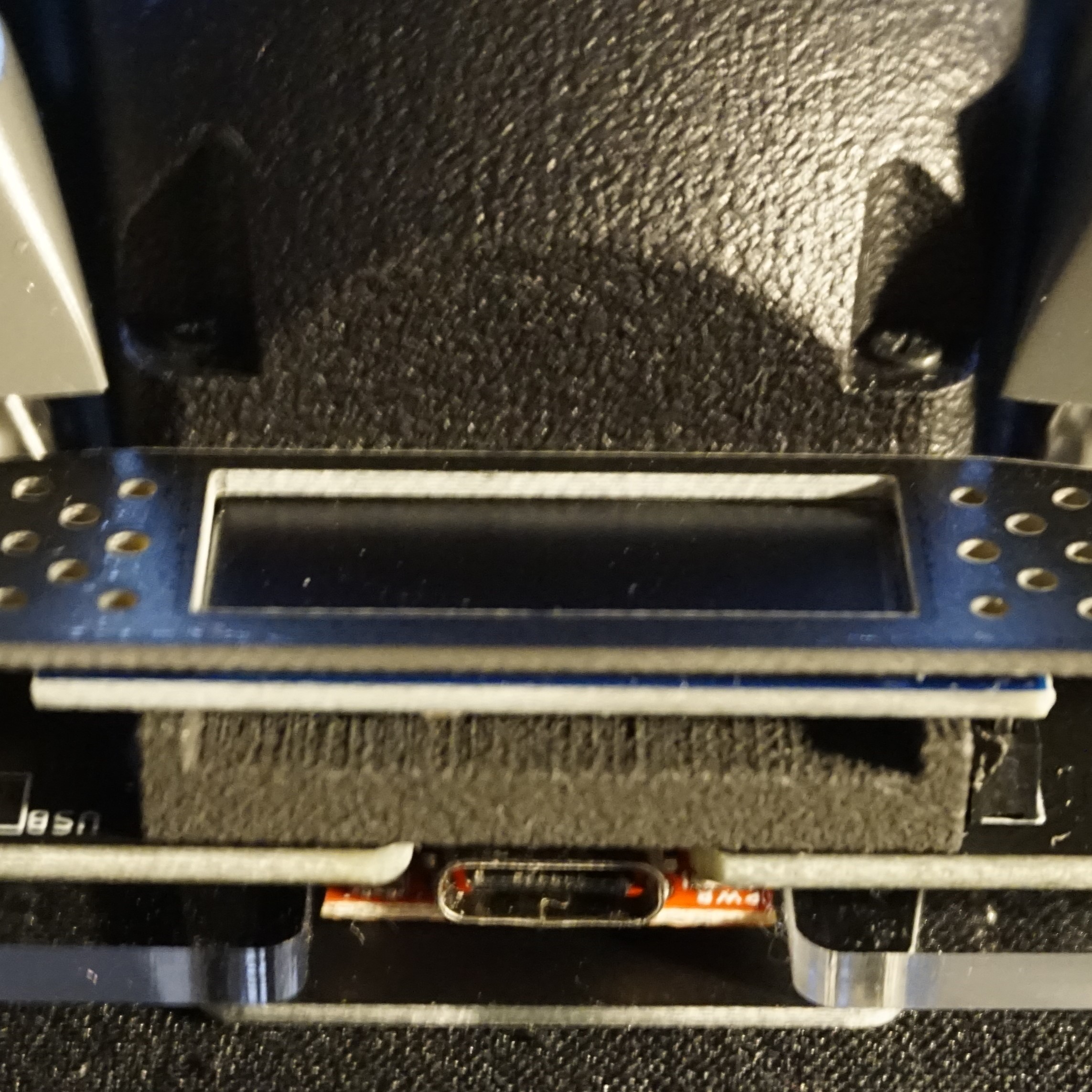
According to the build guide the lens should be secured with masking tape, but a simple lens holder can also be ordered, which holds the lens in place. On Twitter I found another lens holder which is extended so it can also keep the OLED display straight.
Case assembly
As you might have noticed I didn’t take any pictures of the case assembly since the official build guide covers it pretty well. The only thing I would change is to place the 6mm spacers around the trackball area on the PCB before attaching the switch plate and the switches. Since there is very little space to place them afterwards.
Trackball
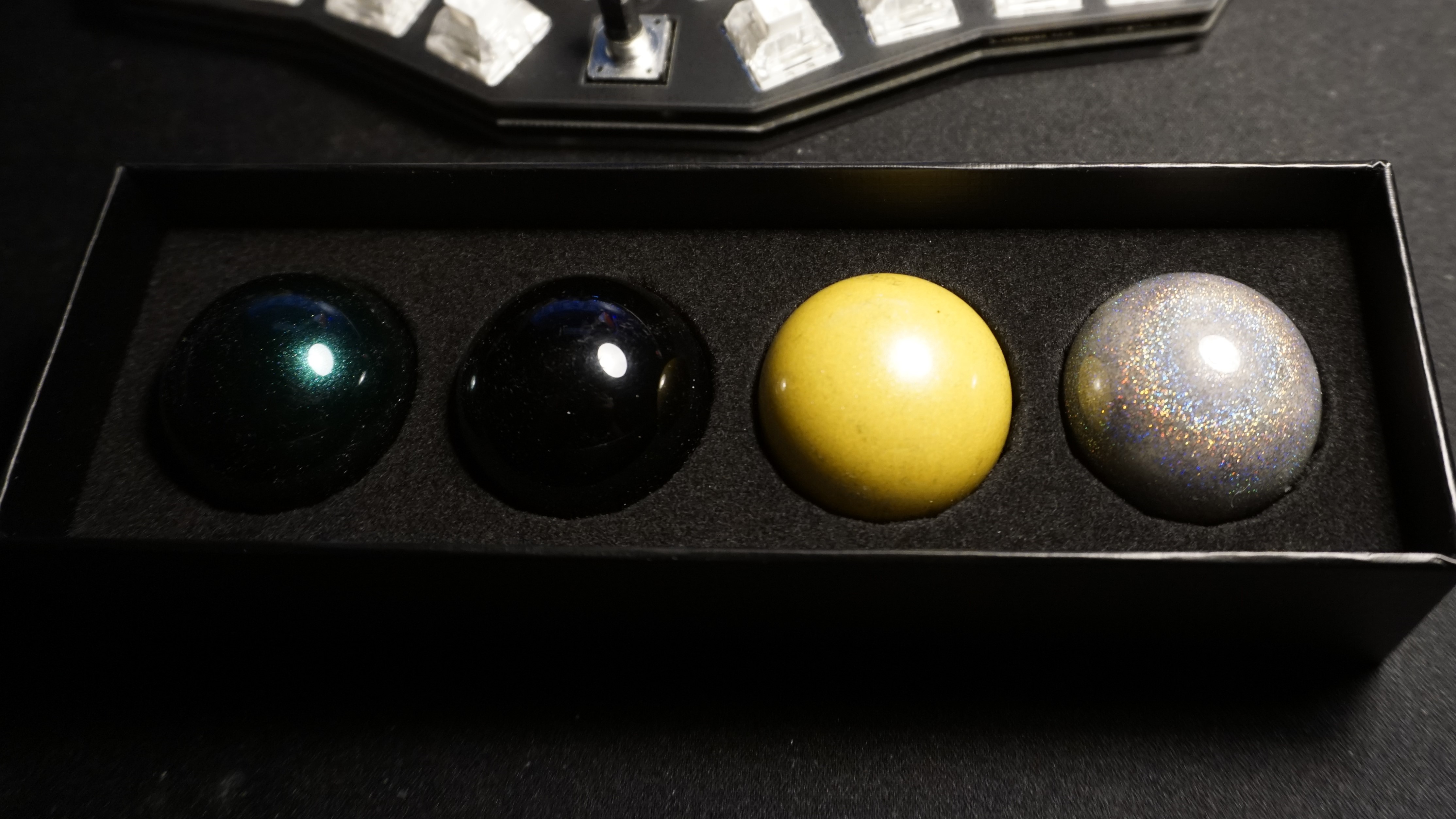
I got a 4-pack of trackballs before I got this keyboard, for the Charybdis, but didn’t use them yet. Since I am using the Susuwatari keycaps, which are grey, I also opted for the grey trackball.
The trackball holder has 3 bearings inside (the white dot), so the trackball can move smoothly.
Converting to RP2040
As I said I wanted to upgrade to an RP2040.
Usually adding
CONVERT_TO=promicro_rp2040
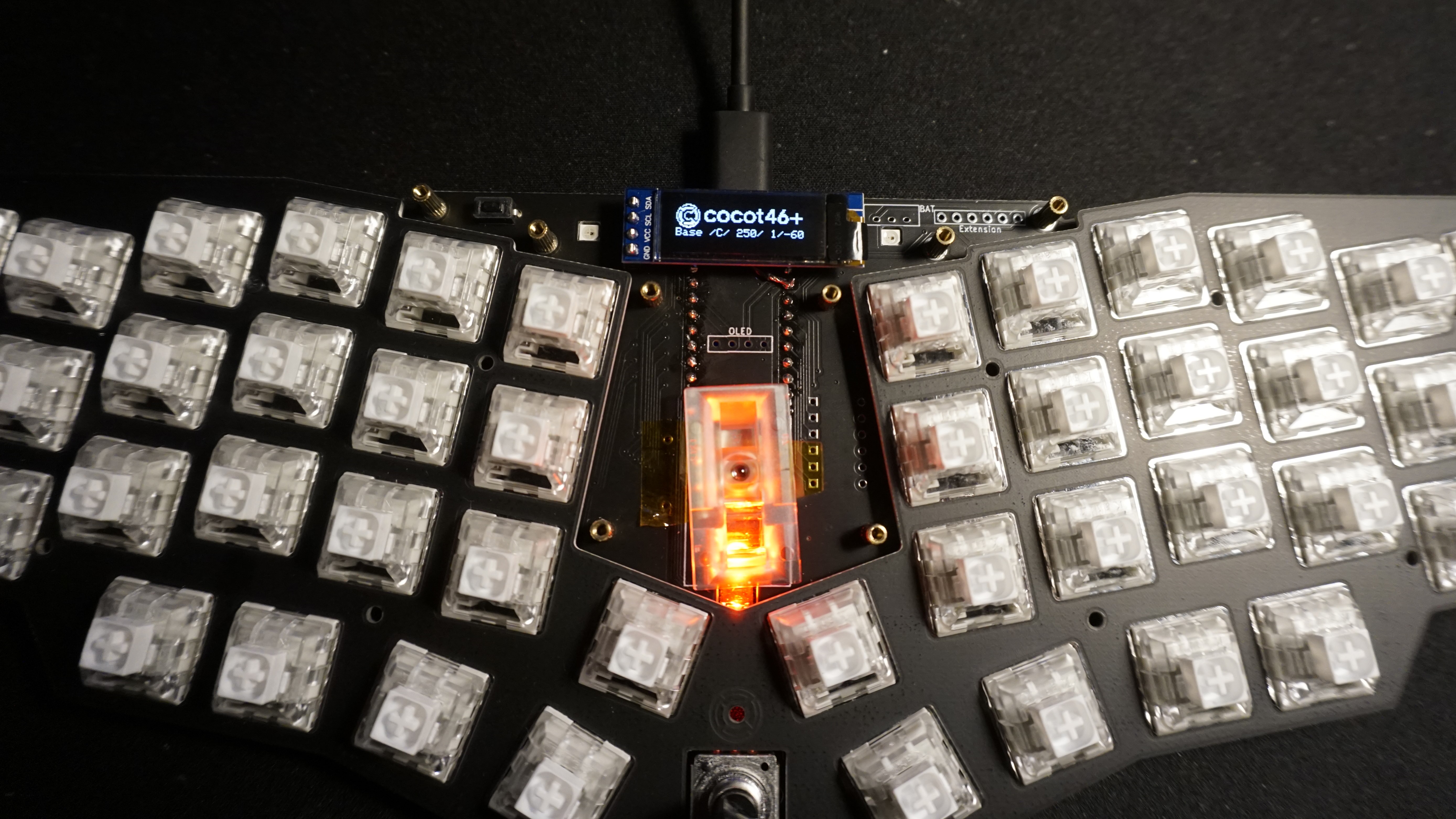
to rules.mk file is enough to convert an existing keyboard. However when I did this the OLED display showed as following:
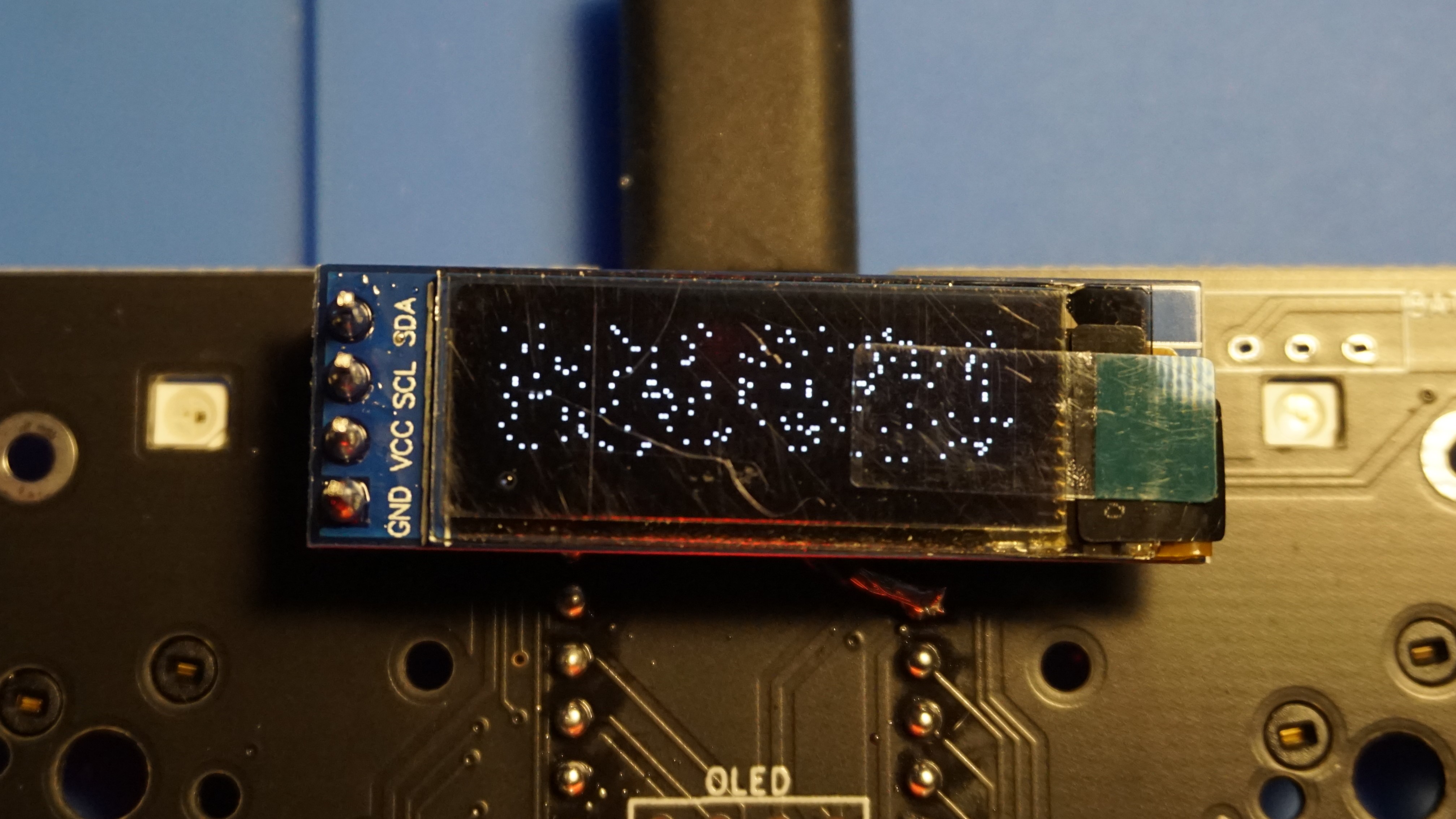
And the trackball would react very choppy and all keys where acting strange, they would be either very delayed or not activate at all. I swapped in an Elite-C to check if it would have the same issues, but it did not.
When enabling debugging on the RP2040 I found the following error coming from the OLED:
> oled_render offset command failed
Which seemed to get spammed and caused the issues.
After consulting with the guys on the QMK Discord it appeared a matrix row pin (D1) is being shared with I2C.
On AVR the I2C controller hijacks the pin whenever it is being activated.
On RP2040 however you are supposed to set the appropriate alternate function for the used pins, and that selection gets overwritten when the matrix code reconfigures the pins as plain GPIOs.
As stated by sigprof on Discord.
I added the changes and my Cocot46plus is now running on RP2040!
Many thanks to bomtarnes, Drashna, sigprof and Dasky from QMK Discord for helping me out with this issue!
The working firmware with the changes can be found here.
3.3V vs 5V
Warning
Update:
Do not do this! This may cause damage to the microcontroller. See Cocot46plus and RP2040
I have personally reverted to using an Elite-C.
The RP2040 has a 3.3V voltage regulator, but since some components (ADNS-5050, SK6812MINI-E RGB LEDs, and EC12 Rotary encoder) have a working voltage of 5V and that’s what the board originally was designed for, I supplied the power from the RAW pin on the RP2040 which provides max 5V at ~600mA instead of the regulated 3.3V 3V3 pin.
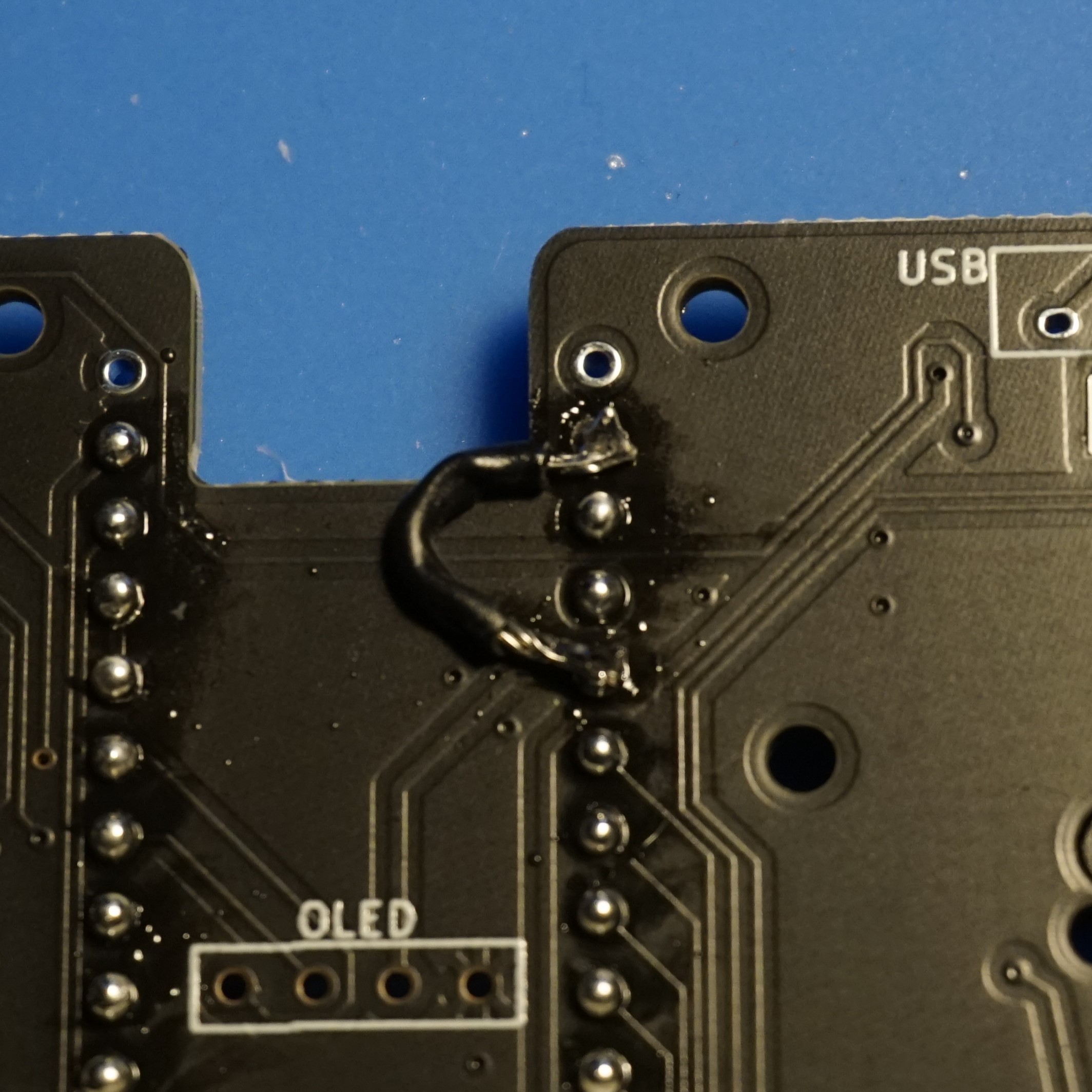
This was done by desoldering the 3V3 pin on the mcu and adding a bodge wire between VCC and RAW pads on the PCB.
Conclusion
Because of the presoldered parts this build was very easy to do. Using spring loaded headers for the MCU would probably make it even easier, but they’re hard to source in Europe. I was glad I socketed the microcontroller however, that way I could easily swap mcus to check if the issues I had were caused by the mcu.
For the RP2040 I did not expect to run into this problem, but luckily it was easily fixed with help. For a future revision it might be nice to upgrade the MCU and use one with more pins so the pins don’t have to be shared.
Besides that I very much like the trackball holder and how it traps the trackball so it doesn’t fall out when holding it upside down. This makes it easier to carry the board around.
Next steps
In my tweet I said my next steps would be to migrate my keymap and upgrade to RP2040. Upgrading can be checked off, so what’s left is migrating my keymap.
Besides that I am still thinking of using Gazzew Boba U4s instead of the Kailh Box Whites, but I’ll decide on that after I migrated my keymap and typed on it for a while.
Other than that I’ll probably add some middle plates and add those.
For those a new post will follow.